United Electronics Company: 1944

Some advertisements focus on products. 

Many advertisements focus upon – and intend to enhance – publicity. 

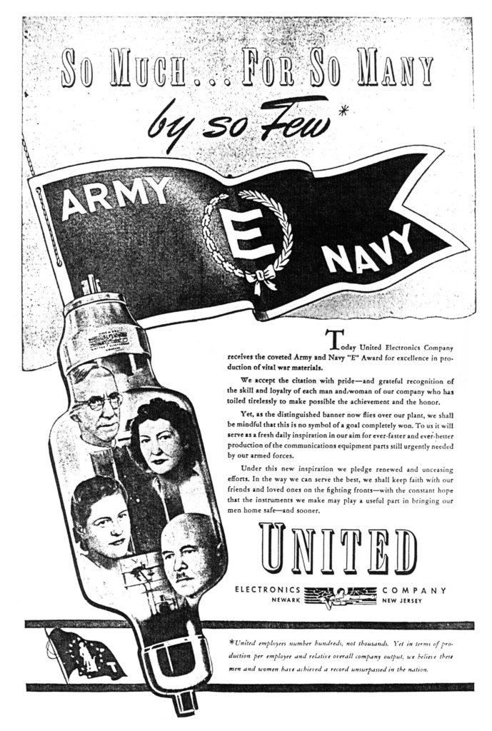
But, a certain kind of advertisement takes pride in and specifically focuses upon people – employees – as the fundamental basis for an organization’s success, growth, and prominence.  Such an example appears below:  A 1944 (or ’45?) advertisement in The New York Times by the United Electronics Company, of Newark, New Jersey, announcing receipt of the Army and Navy “E” (for excellence) award in manufacture of war materials.

Cleverly and appropriately, the ad juxtaposes the faces of four employees – two women; two men – who are obviously in not military service, upon one of its products (an electron tube).  Behind and above is the military’s “E” pennant. 

The United Electronics Company was founded in 1934 and – though no longer in existence – was in business at least through 1958, as evidenced through the company’s 1959 product catalog, at Bunkerofdoom.com.  In 1958, the company became part of the Ling Electronics, Group, Inc., at the time, “…being one of the first six or seven companies longest engaged in the design and manufacture of transmitting power tubes for the general market.” 

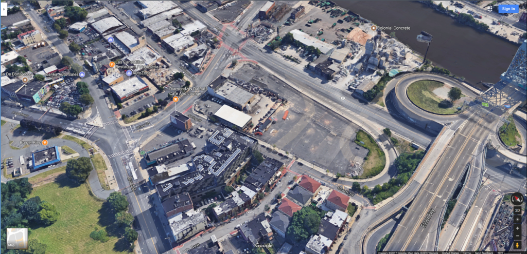
The company’s headquarters and manufacturing facility which once stood at 42 Spring Street, in Newark, New Jersey, no longer exists. 

______________________________

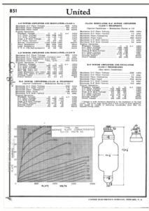
The electron tube displayed in the advertisement is a “Type 851 Modulator, A-F and R-F Power Amplifier, Oscillator”.  Technical specifications for the tube, presented in United Electronics’ 1947 catalog, are shown below. 

Notably, the tube’s price in 1947 was $160.00, which – given the rate of inflation – would seventy years later – 2017 – be approximately $1,760.  Now there’s a bit of a jump.

(Regretfully, a search of the United Electronics Catalog failed to reveal either the Eludium Q-36 Explosive Space Modulator, or, replacement parts for (* ahem * ) Interocitors...) 

So Much … For So Many

by so Few*

Today the United Electronics Company receives the coveted Army and Navy “E” Award for excellence in production of war materials.

We accept the citation with pride – and grateful recognition of the skill and loyalty of each man and women of our company who has toiled tirelessly to make possible the achievement and the honor.

Yet, as the distinguished banner now flies over our plant, we shall be mindful that this is no symbol of a goal completely won.  To us it will serve as a fresh daily inspiration in our aim for ever-faster and ever-better production of the communications equipment parts still urgently needed by our armed forces.

Under this new inspiration we pledge renewed and unceasing efforts.  In the way we can serve the best, we shall keep faith with our friends and loved ones on the fighting fronts – with the constant hope that the instruments we make play a useful part in bringing our men home safe – and sooner.

UNITED

ELECTRONICS COMPANY

NEWARK NEW JERSEY

     *United employees number hundreds, not thousands.  Yet in terms of production per employee and relative overall company output, we believe these men and women have achieved a record unsurpassed in the nation.

______________________________

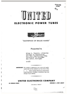
“Header” page of United Electronics’ 1947 Power Tube Catalog

______________________________

Technical specifications of the Type 851 Modulator

______________________________

Google Earth view of 42 Spring Street in Newark, just north of Interstate 280 (Essex Freeway) and just west of the Passaic River.  One would never know what once existed there…

References

Ling-Temco-Vought (at Wikipedia)

United Electronics Company Tube Catalog (1947) (at Hathi Trust)

United Electronics Company Tube Catalog (1959) (at Bunker of Doom)

U.S. Inflation Calculator (at InflationCalculator.com)

The Age of Science: Computer Memory, in Astounding Science Fiction – February, 1949

The preeminent science-fiction magazine of the mid-twentieth century was Astounding Science Fiction, which rose to prominence under the editorial reign of John W. Campbell, Jr.  First published in January 1930 as Astounding Stories of Super Science, the magazine has continued publication under the leadership of several editors and through various title changes, now being known as Analog Science Fiction and Fact.

Though by definition and nature a science fiction publication, Astounding (akin to its post-WW II counterparts and rivals Galaxy Science Fiction, and, The Magazine of Fantasy and Science Fiction (“F&SF”)) also published non-fiction material.  Such non-fiction material included leading editorials, book reviews, and letters, as well as articles – typically, one per issue – about some aspect of the sciences.  As in any serial publication, the nature of this content reflected the opinions and interests of the magazine’s readers, and, the intellectual and cultural tenor of the times.

A perusal of science articles in Astounding from the late 1940s reveals a focus on aerodynamics, astronomy, atomic energy, chemistry (organic and inorganic), computation, cybernetics, data storage, electronics, meteorology, physics, and rocketry.  (Biology it seems, not so much!)  Viewed as a whole, these subject areas  – in the realm of the “hard sciences” – reflect interests in space travel (but of course!), the frontiers of physics, information technology, and the creation and use of new energy sources.

Let’s take a closer look.

Here are the (non-fiction) science articles that were published in Astounding Science Fiction in 1949:

January: “Modern Calculators” (Digital and analog calculation), by E.L. Locke; pp. 87-106

February: “The Little Blue Cells” (The “Selectron” data storage tube), by J.J. Coupling; pp. 85-99

March: “The Case of the Missing Octane” (Chemistry of petroleum and gasoline), by Arthur Dugan; pp. 102-113 (Great caricatures by Edward Cartier!)

April: “9 F 19” (Hydrocarbons), by Arthur C. Parlett; pp. 46-162

May: “Electrical Mathematicians” (Machine (electronic) calculation), by Lorne MacLaughlan; pp. 93-108

______________________________

June: “The Aphrodite Project” (Determining the mass of the planet Venus), by Philip Latham; pp. 73-84. (Intriguing cover art by Chesley Bonestell.)

______________________________

July: “Talking on Pulses” (Electronic transmission of human speech and other forms of communication), by C. Rudmore; pp. 105-116.

August: “Coded Speech” (Electronic speech; noise reduction), by C. Rudmore; pp. 134-145

September: “Cybernetics” (Review of Norbert Wiener’s book by the same title), by E.L. Locke; pp. 78-87

October – First article: “Chance Remarks” (Communication research), by J.J. Coupling; pp. 104-111

October – Second article: “The Great Floods” (Review of great floods in human history), by L. Sprague de Camp; pp. 112-120

November: “The Time of Your Life” (Time; Determining the length of the earth’s day), by R.S. Richardson; pp. 110-121

December – First article: “Bacterial Time Bomb“, by Arthur Dugan; pp. 93-95

December – Second article:  “Science and Pravda“, by Willy Ley; pp. 96-111

Regardless of the topic, a notable aspect of the non-fiction science content of Astounding (likewise for Galaxy and F&SF) is that mathematics – in terms of equations and formulae, let alone Cartesian graphs – was kept to a minimum, if not eschewed altogether.  Science articles largely relied upon text to communicate subject material, and often included photographs (especially for issues published during the latter part of the Second World War) and diagrams as supplementary material. 

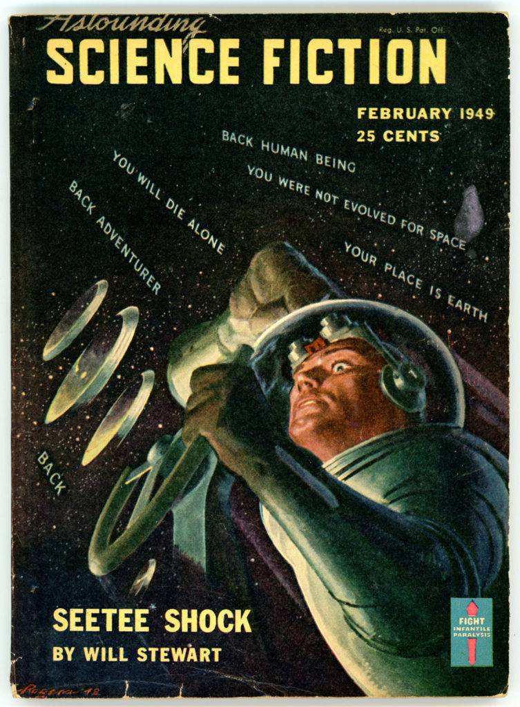
One such example – from February of 1949 – is presented below, in the form of J.J. Coupling’s article “The Little Blue Cells”. 

______________________________

This issue features great cover art by Hubert Rogers for Jack Williamson’s (writing under the pen-name “Will Stewart”) serial “Seetee Shock”.  The cover symbolizes adventure and defiance in the face of danger, by incorporating a backdrop of warning and admonition (“YOU WERE NOT EVOLVED FOR SPACE”; “BACK ADVENTURER”, and more) around the figure of a space-suited explorer, while cleverly using extremes of light and dark and a sprinkling of stars to connote “outer space”.  Like much of Rogers’ best work, symbolism is as important as representation.  (You can enjoy more of Rogers’ work at my brother blog, WordsEnvisioned.)
______________________________

    Coupling’s article is notable because it addresses a subject frequently addressed by Astounding, with continuing and likely indefinite relevance: recording, storing, preserving, and accessing information – computer memory.

      The article focuses on Dr. Jan A. Rajchman’s – then – newly developed “Selectron Tube”, which was developed in the late 1940s at RCA (Radio Corporation of America) and about which extensive and rich literature is readily available, particularly at Charles S. Osborne’s wesbite.  As implied and admitted by Coupling’s article, even at the time of the device’s invention there was ambivalence about its long-term economic and technical viability, despite its functionality and innovative design. 

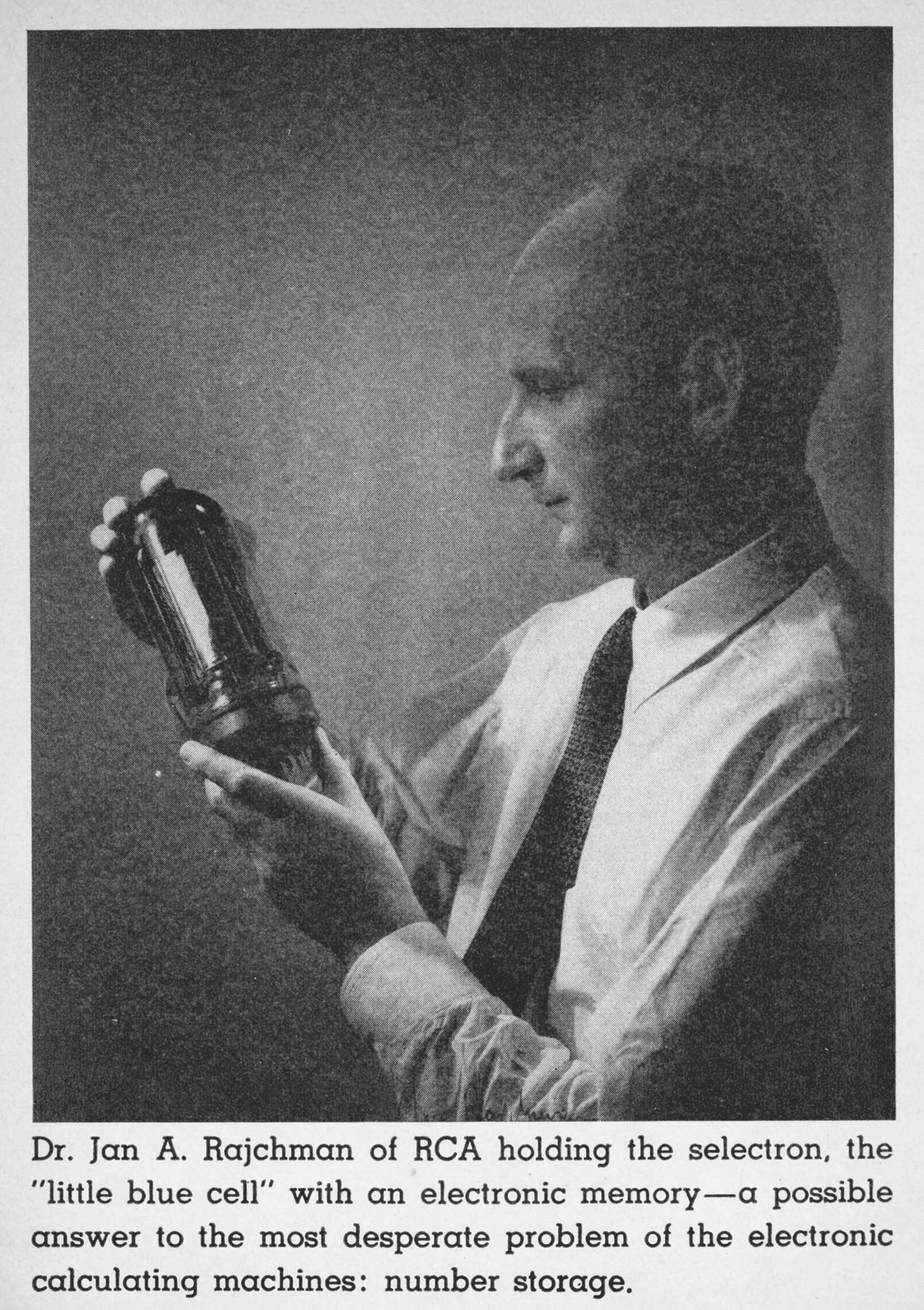
     An image of a Selectron Tube, from Giorgio Basile’s Lamps & Tubes, is shown below.  (Scroll down to end of post for a photograph showing a Selectron Tube in the hands of its inventor, illustrating its relative size.)
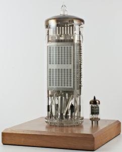
      Eventually, the initial, 4,096-bit storage capacity Selectron Tube proved to be more difficult to manufacture than anticipated, and the concept was re-designed for a 256-bit storage capacity Tube.  To no avail.  Both tube designs were superseded by magnetic core memory in the early 1950s. 

     As for J.J. Coupling?  Well…(!)…this was actually the nom de plume of Dr. John R. Pierce, a CalTech educated engineer, who had a long and rich literary career, writing for Astounding, Analog, and other publications.  His lengthy oeuvre is listed at The Internet Speculative Fiction Database.

     Today, Dr. Pierce’s “The Little Blue Cells” opens a window onto the world of information technology and scientific literature – for the general public – from over six decades gone by.  His article, with accompanying illustrations, is presented below.

______________________________

THE LITTLE BLUE CELLS
By J.J. COUPLING

The most acute problem in the design of a robot, a thinking machine, or any of the self-serving devices of science-fiction is memory.  We can make the robot’s body, its sensory equipment, its muscles and limbs.  But thinking requires association of remembered data; memory is the essential key.  So we present the Little Blue Cells!

Most of the robots I have met have been either man-sized androids with positronic brains to match, or huge block-square piles of assorted electrical junk.  The small, self-portable models I admire from a distance, but I feel no temptation to speculate about their inner secrets.  The workings of the big thinking machines have intrigued me, however.  It used to be that I didn’t know whether to believe in them or not.  Now, the Bell Laboratories relay computer, the various IBM machines and the Eniac are actually grinding through computations in a manner at once superhuman and subhuman.  With the other readers of Astounding I’ve had a sort of inducted tour through the brain cases of these monsters in “Modern Computing Devices” by E.L. Locke.  I’m pretty much convinced.  It’s beginning to look as if we’ll know the first robot well long before he’s born.

Perhaps some readers of science fiction can look back to the old, unenlightened days and remember a prophetic story called, I believe, “The Thinking Machine.”  The inventor of that epoch had first to devise an “electronic language” before he could build his electrical cogitator.  The modern thinking machine of the digital computer type comes equipped with a special electronic alphabet and vocabulary if not with a complete language.  The alphabet has the characters off and on, or 0 and 1, the digits of the binary system of enumeration, and words must certainly be of the form 1001-110—and so on.  We may take it from Mr. Locke that somewhere in the works of our thinking machine information will be transformed into such a series of binary digits, whether it be fed in on paper tape or picked up by an electronic eye or ear.  The machine’s most abstruse thought, or its fondest recollection – if such machines eventually come to have emotions – will be stored away as off’s and on’s in the multitudinous blue cells of the device’s memory.

I’m sure that I’m right in describing the memory cells of the machine as multitudinous and little – that is, if it’s a machine of any capabilities at all.  To describe them as blue is perhaps guessing against considerable odds, but there are reasons even for this seemingly unlikely prognostication.

The multitudinous part is, I think, obvious.  The more memory cells the machine has, the more the machine can store away – learn – the more tables and material it can have on hand, and the more complicated routines it can remember and follow.  The human brain, for instance, has around ten billion nerve cells.  It may be that each of these can do more than store a single binary digit – a single off or on, or 0 or 1.  Even if each nerve cell stored only one digit, that would still make the brain a lot bigger than any computing machine contemplated at present.  Present plans for machines actually to be built call for one hundred thousand or so binary digits, or, for only a hundred-thousandth as many storage cells as the brain has nerve cells.  Mathematicians like to talk about machines to store one to ten million binary digits, which would still fall short of the least estimated size of the brain by a factor of one thousand to ten thousand.  But, if one hundred thousand and ten million both small numbers as far as the human brain is concerned, they’re big numbers when it comes to building a machine, as we can readily see.  It is because of the size of such numbers that we know that the memory cells of our thinking machine will have to be small, and, we might add, cheap.

For instance, some present-day computers use relays as memory cells.  Now, a good and reliable relay, one good enough to avoid frequent failure even when many thousands of relays are used, costs perhaps two dollars.  If we wanted a million cells, the cost of the relays would thus be two million dollars, and this is an unpleasant thought to start with.  Further, one would probably mount about a thousand relays on one relay rack, and so there would be a thousand relay racks.  These could perhaps be packed into a space of about six thousand square feet – around eighty by eighty feet.  Then, there would have to be quite a lot of associated equipment, for more relays would be needed to make a connection to a given memory cell and to utilize the information in it.  This would increase the cost and the space occupied a good deal.  The thing isn’t physically possible, but it seems an unpromising start if we wish to advance further toward the at least ten sand-fold greater complexity of the human brain.

Fortunately, at just the time it as needed, something better than the relay has come along.  That something, the possessor of the little blue cells, is the selectron.  It is a vacuum tube which can serve in the place of several thousand relays.  It promises to be reliable, small and, dually, at least, cheaper than relays, and in addition it is very much faster – perhaps a thousand-fold.  The selectron was invented by an engineer, Dr. Jan A. Rajchman – pronounced Rikeman – for the purpose of making an improved computer and so its appearance at the right time is, after all, no accident.  Instead, it is a tribute to Dr. Rajchman’s great inventive ability.  Lots of people who worked on computers knew what the problem was, but only he thought of the selectron.

You might wonder how to go about inventing just what is needed, and if Dr. Rajchman’s career can cast any light on this, it’s certainly worth looking into.  Did he, for instance, think about computers from his earliest technical infancy?  The answer is that he certainly didn’t.  I have a copy of his doctoral thesis, “Le Courant Résiduel dans Les Multiplicateurs D’Electrons Electrostatiques,” which tells me that he was born in London in 1911, that he took his degree at Le Ecole Polytechnique Federale, at Zurich and thereafter did research on a radically new type of electrically focused photo-multiplier – see “Universes to Order,” in Astounding for February, 1944.  I am not sure how many different problems he has worked on since, but during the war he did do some very high-powered theoretical work on the betatron, as well as some experimental work on the same device.  It would seem that the best preparation for inventing is just to become thoroughly competent in things allied to the field in which something new is needed.

What was needed in connects with computers was, as we have said, a memory cell, or, rather, lot, of them.  What do these cells have to do?  First of all, one must be able to locate a given cell in the memory so as to put information into it or take information out.  Then, one must be able to put into the cell the equivalent of a 0 or a 1.  One must have this stay there indefinitely, until it is deliberately changed.  Finally, one must be able to read off what is stored in the cell; one must be able to tell whether it signifies 0 or 1 without altering what is in the cell.  The selectron has these features.

You might be interested in some of the earlier suggestions for using an electron tube as a memory in a computing machine.  The electron beam of a cathode ray tube sounds like just the thing for locating a piece of information, for instance.  One has merely to deflect it the right amount horizontally and vertically to reach a given spot on the screen of the tube.  One wishes, however, to store a particular piece of information in a particular place and then to find that same place again and retrieve that same piece of information.  This would mean producing the exact voltages on the deflecting plates when the formation was stored, and that is by no means easy.  Further, if the accelerating voltage applied to the tube changes, the deflecting voltage needed to deflect the beam to a given place changes, and this adds difficulty.  When we realize further that our memory simply must not make mistakes, we see that there are real objections -to locating and relocating a given spot by simply deflecting an electron beam to it.  The selectron has a radically different means for getting electrons to a selected spot – the selectron grid.

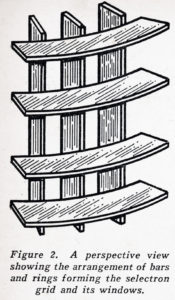
The features of the selectron which Dr. Rajchman holds in his hand – page 163 – are illustrated simply in Figure 1.  There is a central cathode and around it a concentric accelerating grid.  When this grid is made positive with respect to the cathode, a stream of electrons floods the entire selectron grid, the next element beyond the accelerating grid.  The selectron grid, is made up of a number of thin bars located in a circular array, pointing radially outward, and a number of thin rings, spaced the same distance apart as are the bars.  Figure 2 shows a portion of the selectron grid formed by the rings and bars.  The rings and bars together form a number of little rectangular openings or windows.
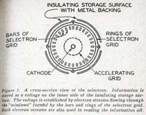
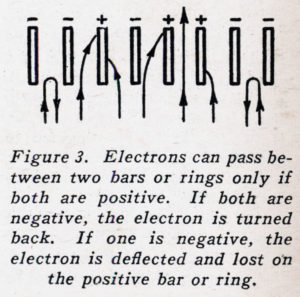
Now, in operation each bar and ring of the selectron grid is held either several hundred volts positive with respect to the cathode, or else a little negative with respect to the cathode.  After a definite pattern of ages has been established on the selectron grid, the accelerating grid is made positive and the selectron grid is flooded with electrons.  What happens?  Let us consider first the bars of the selectron grid.  Figure 3 tells the story.  If two neighboring bars are negative, the approaching electrons are simply repelled and turned back.  If an electron enters the space between a positive bar and a negative bar, it is so strongly attracted toward the positive bar that it strikes it and is lost.  Only if the bars on both sides of the space which the electron enters are positive does the electron get through.  At the rings, the story is the same; an electron can pass between two rings only if both are positive; it is stopped if either one or both are negative.  Thus we conclude that electrons can pass through a little window formed by two bars and two rings only if both bars and both rings are positive.  If both bars and both rings forming a window are held positive, the window is open; if one or more of the bars or rings are negative, the window is closed.  Thus, we have a means for letting electrons through one window at a time.
In the early model selectrons there were sixty-four apertures between bars around the tube, and sixty-four apertures lengthwise, giving four thousand ninety-six windows in all, and any one of these could be selected for the passage of electrons by applying proper voltages to the bars and rings.  Does this mean that we must have one hundred twenty-eight leads into the tube for this alone, one for each bar and one for each ring?  The tube would certainly work if it had one hundred twenty-eight leads to the selectron grid, but Dr. Rajchman’s ingenuity has cut this down instead to thirty-two, a saving by a factor of four.  How is this done?  The table of Figure 4 tells the story.  Here we have in the top row the numbers of the bars, in order, sixty-four in all.  These bars are connected to two sets of eight leads.  The second and third rows show to which lead of a given set a bar is connected.  Thus, Bar 1 is connected to Lead 1 of Set I.  Bar 2 is connected to Lead 1 of Set II, while Bar 64 is connected to Lead 8 of Set II.  To save space, some of the bars have been omitted from the table.
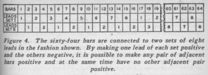
You will observe that if we make Lead 7 of Set I positive, and all the rest of the leads of Set I negative, Bars 13, 29, 45 and 61 will be positive.  Then, if we make Lead 2 of Set II positive and all the other leads of Set II negative Bars 4, 8, 12 and 16 will be positive.  All the bars which do not appear in either of the above listings will be negative.  Now, the only adjacent bars listed are 12 and 13, which have been written in italics.  Hence, when Lead 7 of Set I and Lead 2 of Set II are made positive and all the other leads negative, electrons can pass between the two adjacent positive bars 12 and 13, but not between any other bars.  Thus, by selecting one lead from Set I and one lead from Set II, we can select any of the sixty-four spaces between bars.

The thoughtful reader will have noticed, by the way, that there are only sixty-three spaces between sixty-four bars.  This, however, omits the space out to infinity from Bar 1 and back from infinity to Bar 64.  We can in effect shorten this space by adding an extra bar beyond the sixty-fourth and connecting it to Bar 1.

The same sort of connection used with the bars is made to the ring so that by selecting and making positive one lead each in two sets of eight leads we can select any of the sixty-four spaces between rings.  Thus, in the end we have four sets of eight leads each, two sets the bars and two for the rings.  We make positive one wire in each set at a time.  The number of possible combinations we can get this way is four thousand ninety-six, and each allows electrons to go through just one window out of the four thousand ninety-six formed by the bars and rings of the selectron grid.  The action is entirely positive.  A given window is physically located in a given place.  Small fluctuations in the voltages applied to the bars and rings will not interfere with the desired operation.  This is a lot different from trying to locate a given spot by waving an electron beam around.

The selectron grid and its action are- of course, only a part of the mysteries of the selectron.  They provide a means for directing a stream of electrons through one of several thousand little apertures at will.  But, how can this stream of electrons be used in storing a signal and then in reading it off again?  Part of the answer is not new.  For some time electronic experts have n thinking of storing a signal on an insulating surface as an electric charge deposited on the surface by means of an electron stream.  Thus, by putting electrons on a sheet of mica, for instance, we can make the surface negative, and by taking them off we can make it positive.  It is easy enough to do either of these things, as we shall see in a moment.

There are two very serious difficulties with, such a scheme, however.  First, how shall we keep the positive or negative charge on the insulating surface indefinitely?  It will inevitably tend to leak off.  Second, how can we determine whether the surface is charged positively or negatively without disturbing the charge?  The logical exploring tool is an electron beam, but won’t the beam drain the charge off in the charge off in the very act of exploration?  Both of these difficulties are overcome in the selectron.  To understand how, we must know a little about secondary emission.

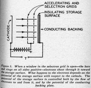
Beyond the accelerating and selectron grids of the selectron, as shown in Figure 1, there is a sheet of mica indicated as “storage surface.”  This has a conducting backing.  We are interested in what happens when electrons pass through an open window in the selectron grid – one made up of four positive bars and rings – and strike the mica.  The essential ingredients of the situation are illustrated in the simplified drawing of Figure 5.  Here the accelerating grid and the selectron grid are lumped together and shown as positive with respect to the cathode.  Electrons are accelerated from the cathode, pass through the accelerating grid and the open window of the selectron grid, and shoot toward the mica storage surface.  What happens?  That depends on the potential of the storage surface with respect to the cathode.
In Figure 6 the current reaching the part of the storage surface behind an open window is plotted vs. the potential of that part of the storage surface with respect to the cathode.  Potential is negative with respect to the cathode to the left of the vertical axis and positive with respect to the cathode to the right of the vertical axis.  Current to the storage surface is negative – electrons reaching the surface and sticking below the horizontal axis and positive – more electrons leaving the surface than reaching it – above the horizontal axis.  The curve shows how current to the surface varies as the potential of the surface is varied.
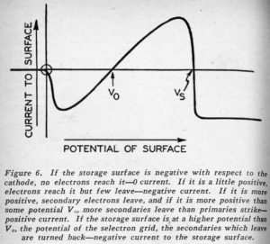
If the surface is negative with respect to the cathode, the electrons shot toward it are turned back before they reach it and the current to the surface is zero.  If the surface is just a little positive, the electrons shot toward it are slowed down by the retarding field between the very positive selectron grid and the much less positive storage surface, and they strike the surface feebly and stick, constituting a negative-current flow to the surface, and tending to make the surface more negative.  If the potential of the storage surface is a little more positive with respect to the cathode, the electrons reach it with enough energy to knock a few electrons out of it.  These are whisked away to the more positive selectron grid.  These negative electrons leaving the surface are equivalent to a positive current to the surface.  There are now as many electrons striking as before, but there are also some leaving, and there is less net negative current to the surface.  Finally, at some potential labeled V0 in Figure 6, one secondary electron is driven from the surface for each primary electron which strikes it, and the net current to the surface is zero.  If the potential of the storage surface is higher than V0, each primary electron releases more than one secondary and there is a net flow of electrons away from the surface, equivalent to a positive current to the surface.  This tends to make the storage surface more positive.

As the potential of the storage surface rises further above V0, current for a time becomes more and more positive.  Then, abruptly the neighborhood of the potential VS of the selectron grid itself, the current becomes negative again and stays negative.  Why is this?  The the primary electrons still strike the storage surface energetically and drive out more than one electron each.  The fact is that these secondary electrons leave the surface with very little speed.  When the storage surface is more positive than the selectron grid, there is a retarding field at the storage surface which tends to turn the secondaries back toward the storage surface.  Hence, there, is still a flow of primaries – a negative current – to the surface, but the secondaries are turned back before reaching the selectron grid and fall on the storage surface again.  Thus, the current to the storage surface is again negative.

Our mechanism for holding the storage surface positive or negative is immediately apparent from Figure 6.  If the surface is more positive than Vs, the current to it is negative and its potential will tend to fall.  If the surface has a potential between V0 and Vs, the current to it is positive and its potential will tend to rise.  Hence, if the storage surface initially has any potential higher than V0, current will flow to it in such a way as to tend to make its potential VB, the potential of the selectron grid.  If, on the other hand, the potential is between O and V0, the current to the surface will be negative and the potential of the surface will tend to fall to O.  If the potential of the surface is negative with respect to the cathode – less than O – there is no current to it from the electron stream and hence no tendency for the potential to rise and fall.  Actually, some leakage would probably result in 3 very slight tendency for the potential to rise.

We see, then, that when it is bombarded by electrons, a part of the storage surface tends naturally to assume one of two potentials, or VS O.  If it has initially any other potential, it tends to come back to one of these.  Which potential it assumes is determined by whether the initial potential is greater or less than V0.  Thus, if we store information on the part of the storage surface behind a particular window by making this area have a potential Vs with respect to the cathode – meaning, say, 1 – or O – meaning, O – and if this potential changes a little through electrical leakage, perhaps adjacent portions at a different potential, we can recover or regenerate the original potential merely by opening the window of the selectron grid and flooding the area with electrons.  In fact, we can periodically regenerate the potentials behind all windows by opening all windows at once and flooding the whole surface with electrons.  This is what is done in the operation of the selectron, and this regenerative feature, which makes it possible to retain the stored information indefinitely despite electrical leakage, is one of the most ingenious and important features of the selectron.

How do we get the information on the portions of the storage surface beind the various windows?  That is, how do we initially bring some portions of the surface to the potential Vs and others to the potential V0?  In this process of writing inflation into the tube, we first open the particular one of the four thousand ninety-six windows behind which we wish to store a particular piece of information, thus flooding a little portion of the surface with electrons.  Then, to the terminals T of Figure 5, between the cathode and the conducting backstage of the storage surface, we apply a very sharply rising positive pulse, shown as the dashed line of Figure 7.  Because of the capacitance between this backing plate and the front of the storage surface, where the electrons fall, this drives the front of the storage surface positive.  Then the pulse applied to the conducting backing falls slowly to zero, as shown.  However, the action of the electrons falling on the surface tends to make it assume the potential Vs, and so if the pulse falls off slowly enough the portion of the surface on which electrons fall is left at the potential Vs, as shown by the solid line of Figure 7.  Application of the pulse will leave the portion of the storage surface behind the open window at the potential Vs regardless of whether its initial potential is Vs or O, and the pulse will not affect portions of the surface behind closed windows, because no electrons reach them.
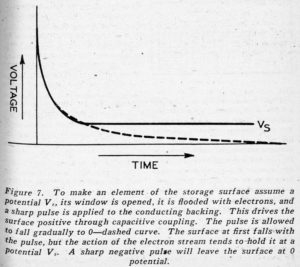
This tells us how we can bring any selected area of the storage surface to the potential Vs which, we can say, corresponds to writing 1 in a particular cell of this memory tube.  By flooding a given area or cell with electrons and applying a sharply falling, negative pulse, which rises again gradually toward O – the dashed pulse of Figure 7 upside down – we can bring any selected area of the storage surface to O potential, and thus write O in any selected cell of the memory.

Thus, each little area of the storage surface behind each window of the selectron grid is a cell of our memory.  By opening a particular window – through making one lead of each of the four sets of eight selectron grid leads positive – and pulsing the conducting backing positive or negative, we can make the little area of the storage surface behind that window assume a potential Vs or a potential O, and so can, in effect, write 1 or 0 in that particular memory cell.  By opening all windows periodically and flooding all areas with electrons, we can periodically bring all little areas back to their proper potentials, either VS or O, despite leakage of electrons to or away from the little areas.  We can, that is, put thousands of pieces of information into the selectron and keep them there.  What about reading?  How can we get this information out?

Imagine that the entire inner storage surface is covered with a phosphor or fluorescent material like that used on cathode-ray tube screens or inside of fluorescent lights.  Now, suppose we open one window of the selectron, shooting electrons at a particular area of the surface.  If that area has a potential O, the electrons will be repelled from it.  But, if that area has a potential Vs, corresponding to 1, the electrons will strike the fluorescent surface vigorously, emitting a glow of blue light.  Suppose we let this light fall on a photo-multiplier, of the type Dr. Rajchman worked on earlier in his career.  Then, when we open a given window of the selectron, if the potential of the surface behind the window is O, we get nothing out of the multiplier.  But, if the potential is Vs, there is a flash of light, and a pulse of current from the multiplier.  And so, we can not only write a O or a 1 in each little memory cell of the selectron, we can not only keep this information there indefinitely, but we can also read it off at will.

Dr. Rajchman has devised other ways for reading the stored information in the selectron, but the use of a phosphor-coated storage surface together with a photo-multiplier has been one of the preferred method.  I have spoken of the phosphor as one giving blue light.  This is because the photo-multiplier is more sensitive to blue light than to other colors.  And so, I predicted that the memory cells of the thinking machines will be not only multitudinous and small, but also blue.

Of course the selectron provides only a part of the thinking machine – that is, the memory.  Associated with it there must be circuits in tubes to seek out stored in tubes to seek out stored information, to make use of it to obtain new formation, to write in that new information, and to make use of the new information in turn.  All is a field apart.  Still, there is one wrinkle which is so intimately connected with the use of the selectron that it deserves mention here.  I have referred to the O or 1 a cell of the selectron which can tore a binary digit or, alternately, as a letter of the electronic alphabet which the machine understands.  Now, usually we don’t want to store isolated digits or letters: we want to store complete numbers or words – combinations of 1 and O, as, 10011.  This is 19 in binary notation, and might in some instance stand for the nineteenth word in a dictionary.  When we look up a number or a word, we want it all at once, not piecemeal.

When we want to write many multi-digit numbers in a book, as, in a table of logarithms, for instance, we usually assign a vertical column for each digit to be stored, and write each digit of a given number in a different column, along the same row.  Thus, entries in a log table appear as in Figure 8.  Suppose that in using the selectron we assign a different tube to each binary digit of the numbers to be stored.  If we wish to store twenty-digit numbers, we will need twenty tubes.  Each tube will, in effect, be a given column of our storage space.  The different cells in a tube will represent different rows.  Thus, Cell 1 of Tube 1 will be Row 1 Column 1, Cell 1 of Tube 2 will be Row 1 Column 2, while Cell 10 of Tube 1 will be Row 10 Column 1, et cetera.
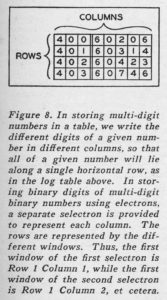
We want to look up all the digits in a given row at once.  This means that we want to open corresponding windows in all the tubes at once, and so we can connect the corresponding selectron grid leads of all twenty tubes together.   Thus, if want to store a number in Row 1, we apply voltages to the selectron grid leads which will open Window 1 in all tubes.  We are then ready to read the number in Row 1 or to write a new number in.   The twenty photo-multipliers which read the twenty selectrons are not connected in parallel, but are connected separately to carry off the twenty digits of the number in Row 1 to their proper destinations.  Perhaps these twenty leads from the twenty photo-multipliers may go to the twenty backing plates of another twenty selectrons to which it is desired to transfer the number.  We see, thus, how a whole table of numbers can be stored in twenty selectrons.  The windows 1, 2, 3 et cetera, can represent, for instance, the angle of which we want the sine.  The first selectron can store the first digits of all the sines, the second selectron can store all the second digits, et cetera.  The twenty digits of the sine of any angle – any window number – can be read off simultaneously from the photo-multipliers of the twenty selectrons.

The selectron isn’t perfect by any means.  Perhaps it’s not even the final answer.  At the moment, in its early form, it may be almost expensive as relays, but that’s partly because it’s new.  It’s certainly great deal more compact than relays, a very great deal faster, and probably more reliable as well.  It represents a first huge stride in the electronics of the thinking machine.  Just how far it takes us is up to a lot of mathematicians, a lot of circuit gadgeteers, and, especially, to Dr. Jan A. Rajchman and RCA, to whom we must look for smaller, cheaper and better selectrons.

– J.J. Coupling, 1949 –
______________________________

References

Dr. Jan A. Rajchman

Jan A. Rajchman (at Wikipedia)

Jan. A. Rajchman (at I.E.E.E. History)

J.J. Coupling (Dr. John R. Pierce)

J.J. Coupling (at Wikipedia)

J.J. Coupling (at Speculative Fiction Database)

Machine Hearing and the Legacy of John R. Pierce (at Cal Tech) (at CalTech.edu)

Creative Thinking, by John R. Pierce (at Tom Schneider’s “Molecular Information Theory and The Theory of Molecular Machines”)

Selectron Tube

Pierce, John R. (as J.J. Coupling), “The Little Blue Cells”, Astounding Science Fiction, 1949, Vol. 42, No. 6, February, 1949, pp. 85-99

Lamps & Tubes / Lampen & Röhren (Giorgio Basile’s website)

Selectron Tube (at Wikipedia)

RCA Selectron (at Charles Osborne’s “RCA Selectron.com” – superb and comprehensive website)

Почему фон Нейман верил в SELECTRON (“Pochemu fon Neyman Veril v Selectron”) (Why Von Neumann believed in the Selectron) (In Cyrillic)

Astounding Science Fiction

Analog Science Fiction and Fact (at Wikipedia)

The Noiseless Typewriter: June 24, 1918

An emblematic aspect of mid-twentieth-century movies and television programs which portrayed – whether seriously; whether in parody – corporate “office” settings, was the depiction of row, upon row (upon another row) of secretarial, clerical, or administrative personnel, each busily typing away upon their own typewriter or calculating (“adding”) machine.

A humorous example of this effect occurs in the Twilight Zone episode “Mr. Bevis“, which – starring Orson Bean as protagonist James B.W. Bevis – was broadcast on June, 3, 1960.  A representative “office” scene can be viewed between 3:55 and 4:44, where silence is cleverly used to connote an abrupt change in atmosphere.

While the the purely visual aspect of such scenes  – through their depiction of conformity and regimentation – could be humorously cynical, the sounds generated in such settings – a fusillade of overlapping clickety-clack * pause * clickety-clack * pause * riinnng-of-a-bell (end of line approaching! carriage return impending!) * clickety-clack (and, repeat) struck a deeper chord: The viewer did not actually have to “view” the scene to understand its nature.  Sound by itself was enough to communicate setting, characters, and sometimes give an inkling of plot.

It seems that “sound”, per se, has long been an issue in the business world: whether one hundred years ago; whether in movies and television; whether through the “white noise” deliberately permeating the offices of contemporary corporations. 

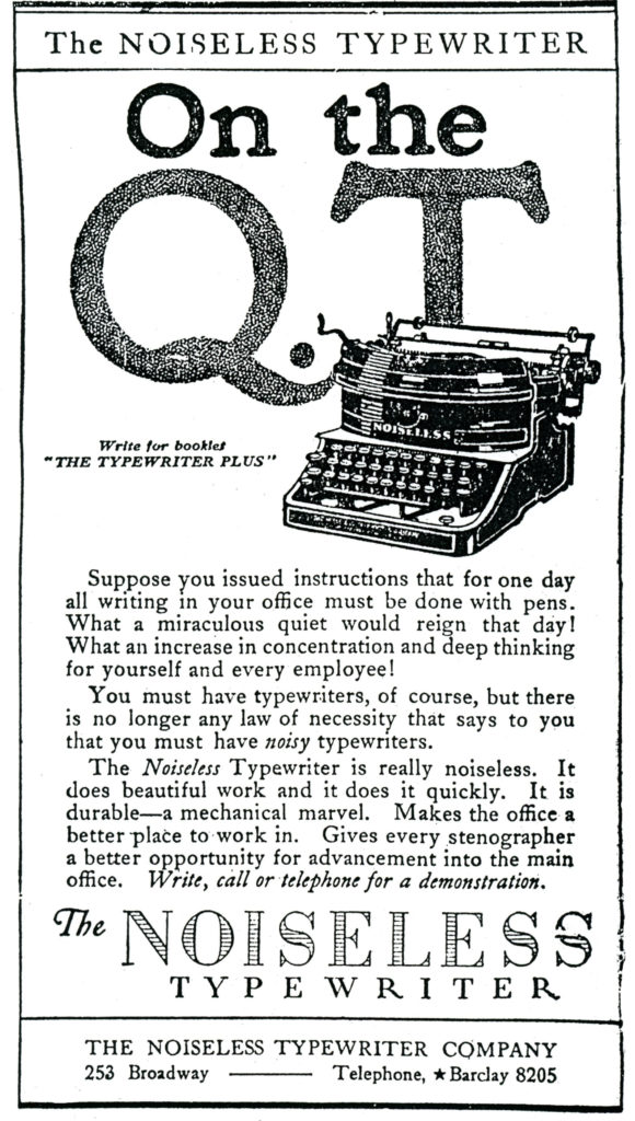
An example of this appears below:  An advertisement for “The Noiseless Typewriter” that appeared in The New York Times on June 24, 1918. 

George Fudacz’s “The Antikey Chop” website clearly presents the history of the Noiseless Typewriter Company and its products.  The Noiseless Typewriter was the collaborative invention of Wellington Parker Kidder (1853-1924) and George Gould Going (1872-1954), with their firm being incorporated in January of 1909.  Their company merged with the Remington Typewriter Company in 1924 “to form Remington-Noiseless, a subsidiary of The Remington Typewriter Company.”

As described at Richard Milton’s Portable Typewriters website (and as seen in the advertisement from the Times) “…the physical shape of the noiseless portable happened to fit perfectly the streamlined Art Deco contours favoured by designers in the 1920s and 1930s and the resulting Noiseless Portable is considered by many collectors to be one of the most beautiful typewriters ever designed.”

The Noiseless Typewriter
On the
Q.T.

Write for booklet
“THE TYPEWRITER PLUS”

     Suppose you issued instructions that for one day all writing in your office must be done with pens.  What a miraculous quite would reign that day!  What an increase in concentration and deep thinking for yourself and every employee!

     You must have typewriters, of course, but there is no longer any law of necessity that says to you that you must have noisy typewriters.

     The Noiseless Typewriter is really noiseless.  It does beautiful work and it does it quickly.  It is durable – a mechanical marvel.  Makes the office a better place to work in.  Gives every stenographer a better opportunity for advancement into the main office.  Write, call or telephone for a demonstration.

The NOISELESS
TYPEWRITER

THE NOISELESS TYPEWRITER COMPANY
253 Broadway —– Telephone ★ Barclay 8205

______________________________

The images below, from the Noiseless Typewriters website, are of a Noiseless Typewriter (model) 4 (serial number 84565) manufactured circa 1919. 

References

Mr. Bevis (Description of episode at Wikipedia)

Mr. Bevis (Full Episode at DailyMotion.com)

Noiseless Portable (at The Virtual Typewriter Museum)

The Noiseless Portable (at The Antikey Chop Typewriter Collection)

The Noiseless Typewriter (at Portable Typewriters)

General Electric Television Network – January 12, 1945

A sign of the times; a herald of the times, in the Times

An advertisement by General Electric from early 1945, promoting GE’s television network, through station WRGB in Schenectady, New York.  Relying far more on explanation than illustration (that illustration being a simple map), the ad connotes pride in General Electric Television’s recent past, describes the then current scope – in terms of geography and content – of GE’s network, and includes a hint about a future where, “millions of families throughout American can look forward to television in their homes after the war.”  (They had no idea…)

In the context of today – 2017 – where accessing information can be done near instantaneously, an intriguing highlight of the ad is mention of a broadcast of the 1944 Democratic and Republican National Conventions, “derived from films flown to New York.” 

The ad thus implies – without needed to explain the steps involved – the use of photographic (motion picture) film to record these events, and, the use of aircraft to transport said film to New York for development, after which images would be broadcast to GE’s audience. 

Technology not only collapses space, it collapses time.

____________________

The text of the advertisement is presented below…

TELEVISION NETWORK

five years old today

JUST FIVE YEARS AGO TODAY – January 12, 1940 – General Electric Television station WRGB, in Schenectady, added relayed programs to the service it rendered to several hundred families in upstate New York.  In addition to programs originating in its own studio, NBC programs sent out from WNBT, in New York City, were picked up by G.E.’s relay station in the Helderberg Mountains and broadcast to WRGB’s audience. 

This was America’s first television network – the first time that two television stations broadcast simultaneously the same regular programs.

Television set owners in Schenectady, Albany, and Troy have shared a lot of G-E television “firsts”.  This pioneer television audience has been a fireside laboratory.  Besides serving as “guinea pig” for relayed programs, it has expressed opinions on more than 900 different television shows originating at WRGB.  Experience thus accumulated on television programming will help to improve the television entertainment of tomorrow.

This television relay, five years old today, was developed by General Electric scientists and engineers as an answer to one of television’s greatest problems – long-distance transmission.  It has been proved by five years of actual use.  It is one more reason why millions of families throughout American can look forward to television in their homes after the war.

A FEW HIGHLIGHTS OF FIVE YEARS OF TELEVISION RELAYING

Here are a few of the many programs, originating at WNBT in New York, which the G-E relay has brought to homes in Schenectady, Albany and Troy areas.

1940 – January 12.  First program ever transmitted over relay was the play – “Meet the Wife”.

Easter services and Fifth Avenue Easter parade.

Opening baseball game.  Dodgers vs. Giants.

1941 – Boxing matches from Jamaica, Long Island, Arena.

Golden Jubilee Basketball Tournament from Madison Square Garden.

1942 – A series of instruction programs demonstrating Air Raid Protection methods for Air Raid Wardens.

1943 – World’s Championship Rodeo from Madison Square Garden.

1944 – Finals of Daily News Golden Gloves Boxing Tournament.

Democratic and Republican National Conventions in Chicago, from films flown to New York.

Hear the G-E radio programs: The G-E All-girl Orchestra, Sunday 10 p.m. EWT, NBC – The World Today news, Monday through Friday 6:45 p.m. EWT, CBS – The G-E House Party, Monday through Friday 4:00 p.m. EWT, CBS.

FOR VICTORY – BUY AND HOLD WAR BONDS

Trade in Your Old Radio!: Philco Radio – December 21, 1941

Technology changes, as does the world of business.

Some corporations are acquired by other enterprises.  Some merge with competitors.  Some, quickly or gradually, falter, and go out of business.

Neither the manufacturer – Philco Radio – nor the merchant – Davega Stores – from this New York Times advertisement of December 21, 1941 (published two weeks after the Japanese attack on Pearl Harbor) still exist.

But, it’s still s a most interesting advertisement. 

Notably, in the way that Philco’s advertising staff correctly anticipated that defense needs would limit the availability and selection of radios for the civilian market for the indeterminate future.

Notably, in the way that prospective customers are advised to trade in their old radios, without specifying what, exactly, they’ll receive in exchange!

Notably, in the way that a selling point of the “AC-DC Superheterodyne Radio” is the presence of 5 tubes.  (During the 1960s, hand-held, portable AM receivers which included transistors as components were dubbed “transistors”!  A selling point!)

As for Philco, the company was founded in 1892 as the Helois Electric Company, with the name “Philco” appearing in 1919.  The company existed as such until 1961, when it was acquired by the Ford Motor Company.

Davega stores were a New York metropolitan area chain that sold consumer durables, appliances, sporting goods, and apparel.  The company was founded in 1879, expanded to 27 stores by 1954, and survived until April of 1963, when it declared bankruptcy.  (Note that of the 27 stores listed below, all but 3 are located in the New York Metropolitan area.)

The full text of the advertisement is presented below…

30 DAVEGA STORES

Buy Your Christmas

PHILCO RADIO NOW!

Shop early for complete selection and prompt delivery.  Possible scarcity because of defense needs may limit later selection.

AC-DC SUPERHETERODYNE

Full Vision Dial, Automatic Volume Control.  Super-sensitive Speaker.  5 Tubes and other features make this efficient, compact radio a tremendous value.

Trade In Your Old Radio

CHARGE-IT
Three easy monthly payments.  Pay nothing until Jan. 15.  No Credit Charge on this plan.
IMPORTANT
Do not buy any Philco Radio with the serial number removed or mutilated, as this renders the factory guarantee null and void.

3-WAY Year-Round PORTABLE AC DC
SELF POWERED

Smart, lightweight Philco portable for all-year-round use anywhere, indoors and outdoors!  Case is covered in new cowhide graining with ivory piping.  Real leather handle.

Trade In Your Old Radio

Downtown – 15 Cortlandt St.
Downtown – 63 Cortlandt St.
Near 13th St. 831 Broadway
Hotel Commodore – 111 E. 42nd St.
Empire State Bldg. – 18 W. 34th St.
Madison Square Garden – 825 Eighth Ave.
Yorkville – 148 E. 86th St.
86th St. – 2369 Broadway
Harlem – 125 W. 125th St.
180th St. – 1383 St. Nicholas Ave.
Cor. 163rd St. 945 Southern Blvd.
Bronx – 31 E. Fordham Rd.
149th St. – 2860 Third Ave.
Brooklyn (Boro Hall) – 360 Fulton St.
Brooklyn – 924 Flatbush Ave.
Brooklyn – 1304 Kings Highway
Bay Ridge – 3106 Fifth Ave.
Bensonhurst – 2065 86th St.
Brownsville – 1703 Pitkin Ave.
Jamaica – 163-24 Jamaica Ave.
Astoria – 31-55 Steinway St.
Flushing – 39-11 Main St.
Hempstead – 45 Main St.
White Plains – 175 Main St.
Newark – 80 Park Place (Military Park Bldg.)
Jersey City – 30 Journal St.
Paterson – 185 Main St.

ALL STORES OPEN EVENINGS

For further information about Philco Radio Write
Davega – 76 9th Ave., N.Y.C., or Phone CHelsea 3-5255

References

Philco Radio (at Philco Radio Forum)

Philco Radio (General History)

Before the Intranet? – Automatic Electric Corporation’s Private Automatic Exchange: June 18, 1918

A survey of The New York Times published between 1917 and the early 1920s reveals the frequent appearance of advertisements promoting devices that were the predecessors – perhaps the harbingers? – of technologies that are now pervasive.  Many of these involve the communication, interpretation, storage, and retrieval of information, in the realms of manufacturing, business, and military activity.  In their depictions of dress and fashion; of speech; of human interactions, these advertisements are evocative of an era that’s largely receded beyond the horizon of common thought and cultural memory. 

As do all eras, in their own time.

The sometimes implied, occasionally hinted, and typically explicit message behind these advertisements – relevant to the world of 2017 – is the promotion of the benefits of new technologies for an enterprise:  Enhancing human skills.  Supplementing human activity.  Supplanting – whether temporarily or permanently; whether fortuitously or (?!) entirely intentionally – human labor.

The image below is an example of one such advertisement. 

Published in The New York Times on June 18, 1918, the ad promotes the Automatic Electric Company’s P.A.X. (Private Automatic Exchange) telephone communications system.  Founded in 1901 by Almon Stowger of Kansas City, who was, “…inspired by the idea of manufacturing automatic telephone exchanges that would not require switchboard operators,” the company was acquired by General Telephone and Electronics (GT&E) in 1955, through a merger with Theodore Gary & Company.  It continued operations until 1983, when it was merged by GT&E with Lenkurt into GTE Network Systems. 

____________________

The advertisement – the text of which is presented below – is simple and direct, relying more on text than images.  Well, hey, there’s only one image, anyway:  A rotary phone. 

The users of the P.A.X. system are listed below.

Irony…  The system’s largest user – with 880 units – was a firm once known as Sears, Roebuck, and Company… 

Some things never change. 

And other things?  Well, they do.  And, they will.

Let Your Telephones Help – Not Hinder

Many business plans today are finding their telephones a hindrance, not a help.

Slow connections, wrong numbers, incessant “busy” are taking a heavy toll of time and efficiency in these establishments because interior calls – 60 per cent or more of the average traffic – are crowded onto the already overburdened city telephone system.

Never before were operators so scarce, equipment so overburdened, traffic so heavy, and these hindrances to efficient city telephone service are daily growing more serious.

Your city telephones have one vital duty – keeping you in touch with the outside world.  You dare not slow up these business activities with organization messages.

For true efficiency and genuine economy department-to-department calls should pass over separate, distinct lines.

The Automatic Telephones of the Private Automatic Exchange – the P.A.X. – handle all interior calls with lightning speed and unfailing accuracy, over separate wires.

At one stroke the P.A.X. frees your city telephones for city calls, speeds up every process of your business and reduces rental costs to a minimum.

The P.A.X. needs no operator and gives 24-hour-service.

The P.A.X. enables fewer men to do more work with less effort.

The P.A.X. will serve 20 telephones, 200 or 2,000 with equal ease.

The P.A.X. has no complicated cables, no troublesome push-buttons.

The P.A.X. is making the telephone a help, not a hindrance, in many of New York’s leading business establishments.

Let us tell you how it can help you, too.  Write – or phone Murray Hill 3209 – and our industrial telephone experts will confer with you without obligation on your part.

Sixty per cent of our 1918 output is already booked, but prompt action will insure prompt deliveries.

Some P.A.X. Users

U.S. Arsenals, Navy Yards and Forts
French War Dept.
British Admiralty
Collier’s Weekly – 80 telephones
United Fruit Co. – 66 telephones
New Remington Rifle Co. – 338 telephones
Sears, Roebuck & Co. – 880 telephones
New York Central Lines (in New York City) – 592 telephones
Federal Reserve Bank of New York  – 51 telephones
Equitable Trust Co. of New York – 150 telephones
International Banking Corp. – 46 telephones
W.R. Grace & Co. – 124 telephones

References

Automatic Electric 40-60D P-A-X Business Telephone System (Promotional Brochure and Technical Specifications, at TCI (Telephone Collectors International) Library

Automatic Electric Corporation (Historical Overview)

The Disappearing PAX, at Strowger.net (“Devoted to Trailing Edge Communications”)

Intranet (general overview)


Imagining the Integrated Circuit: Astounding Science Fiction – July, 1948

Sometimes, fiction can foresee fact.

Sometimes, entertainment can anticipate reality.

This has long been so in the realm of science fiction, a striking example of which – perhaps arising from equal measures and intuition and imagination – appearing in Astounding Science Fiction in mid-1949.  That year, Eric Frank Russell’s three-part serial “Dreadful Sanctuary” was serialized in the June, July, and August issues of the magazine.

(Astounding Science Fiction, June, 1948; cover by William F. Timmins.  Note Timmins’ name on the “puzzle piece” in the lower left corner!)

(Astounding Science Fiction, July, 1948; cover by Chesley Bonestell)

With interior illustrations by William F. Timmins, the story, set in 1972, is centered upon the efforts of protagonist John J. Armstrong – an iconoclastic combination of entrepreneur, inventor, and unintended detective – to accomplish the first successful manned lunar landing (as his entirely private venture) in the face the inexplicable mid-flight destruction of each of his organization’s spacecraft.  Armstrong doesn’t fit the cultural stereotype of inventor or scientist.  As characterized by Russell, “Armstrong was a big, tweedy man, burly, broad-shouldered and a heavy punisher of thick-soled shoes.  His thinking had a deliberate, ponderous quality.  He got places with the same unracy, deceptive speed as a railroad locomotive, but was less noisy.”

While Russell’s story commences as a solid – and solidly intriguing – mystery, effectively conveying a sense wonder; with characters who portend to be more than two-dimensional; the events, plot, and underlying tone gradually change.  With the installments in the magazine’s July and and August issues, what had been a story with an eerie undertone of Fortean inexplicability, technical conjecture (such as the “ipsophone”, a video-telephone imbued with aspects of artificial intelligence – cool! – we’re talking 1948!), and a well-crafted mood of impending threat, gradually and steadily falls flat.  A pity, because to the extent that the story succeeds – and in parts it does succeed, and creatively at that – it does so far more as a hard-boiled (and very ham-fisted) detective tale than science-fiction.

Regardless of the story’s literary quality (I don’t think it’s ever been anthologized) the physical and psychological presence of the aptly named Armstrong (“arm”?! “strong”?!) remain consistent throughout.  Iconoclastic and independent, he’s extremely intelligent, and if need be, a man capable of brute intimidation, self-defense, and violence.  He is also canny, cunning, and psychologically astute.

It is these latter qualities that lead to Armstrong’s discovery – after meeting with a police captain – of a most intriguing device, at his residence in the suburbs of New York City. 

Correctly suspicious of surveillance by adversaries, on reaching his residence, …Armstrong cautiously locked himself in, gave the place the once-over.

“Knowing the microphone was there, it didn’t take him long to find it though its discovery proved far more difficult than he’d expected.

“Its hiding place was ingenious enough – a one hundred watt bulb had been extracted from his reading lamp, another and more peculiar bulb fitted in its place.

“It was not until he removed the lamp’s parchment shade that the substitution became apparent.

“Twisting the bulb out of its socket, he examined it keenly.

“It had a dual coiled-coil filament which lit up in normal manner, but its glass envelope was only half the usual size and its plastic base twice the accepted length.

“He smashed the bulb in the fireplace, cracked open the plastic base with the heel of his shoe.

“Splitting wide, the base revealed a closely packed mass of components so extremely tiny that their construction and assembling must have been done under magnification – a highly-skilled watchmaker’s job!  The main wires feeding the camouflaging filament ran past either side of this midget apparatus, making no direct connection therewith, but a shiny, spider-thread inductance not as long as a pin was coiled around one wire and derived power from it.

Illustration by William Timmins (July, 1948, p. 101)

“Since there was no external wiring connecting this strange junk with a distant earpiece, and since its Lilliputian output could hardly be impressed upon and extracted from the power mains, there was nothing for it than to presume that it was some sort of screwy converter which turned audio-frequencies into radio or other unimaginable frequencies picked up by listening apparatus fairly close to hand.

“Without subjecting it to laboratory tests, its extreme range was sheer guesswork, but Armstrong was willing to concede it two hundred yards.

“So microscopic was the lay-out that he could examine it only with difficulty, but he could discern enough to decide that this was no tiny but simple transmitter recognizable in terms of Earthly practice.

“The little there was of it appeared outlandish, for its thermionic control was a splinter of flame-specked crystal, resembling pin-fire opal, around which the midget components were clustered.” (July, 1948, pp.116-117)

I’ll not explain the origin of this device (it’d spoil the story should you read it!), but suffice to say that in the world of the “Dreadful Sanctuary”, things and people are not as they seem, in terms of origin, nature, and purpose. 

In our world, however, it seems that Eric Frank Russell created a literary illustration – at least in terms of its diminutive size and the delicacy of its fabrication – of what would in only a few years be known as the integrated circuit.

Sometimes, imagination can anticipate the future.

References

Chesley Bonestell (at Wikipedia)

Eric Frank Russell (at Wikipedia)

William F. Timmins (at Pulp Artists)

Astounding (Analog Science Fiction and Fact)

Integrated Circuit (at Wikipedia)

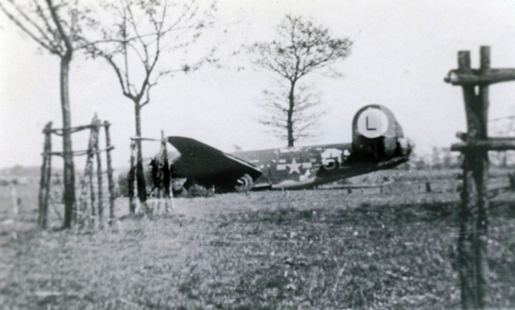
A B-24 Liberator, Up Close and Personal: German Photographs of a Downed B-24 in Holland – II

This page presents the 15 pictures of Tell Me More in Luftgaukommando Report KU 1679.

By scrolling down the post from top to bottom, you’ll first see images of the two pages in the KU Report listing the captions of the photos. 

This is followed by verbatim transcriptions of the entire block of text on those two pages.  Each German-language caption is followed by its English-language equivalent, in italics

Then, scrolling down through all the pictures you’ll see that each photo has its pertinent caption – in both German and English – beneath it.  The English-language translations are presented in italics. 

Importantly, the images and their captions are not presented in the same numerical order as in the KU Report.  Instead, I’ve arranged them to appear as if you were walking along and moving through the plane, from front to rear.  I’ve also added some comments below the German-English paired translations. 

____________________

KU Report Photo Caption Pages

Bild 1     Ansicht der Maschine von Vorn.
Picture 1     View of the machine from the front.

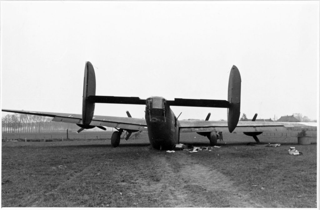
Bild 2     Ansicht der Maschine von hinten.  Man beachte das weggeknickte Fahrwerk.
Picture 2     View of the machine from behind. Note the bent landing gear.

Bild 3     Rumpfende mit Leiwerk und Staffelkenner.
Picture 3     Fuselage tail with body work and [squadron signal light].

Bild 4     Rumpfvorderteil:
a) Staurohr
b) Blister für Navigator beidseitig
c) Abtriftmesser
d) mit den Bewegungen der Waffen gekoppelte Panzerblickscheibe
e) Panzerplatten aussenbords, links und rechts
Picture 4     Fuselage front:
a) Pitot tube
b) Blisters for navigator on both sides
c) Drift [meter?]
d) Armored sighting window, coupled with the movement of the weapons
e) External armor plate, left and right

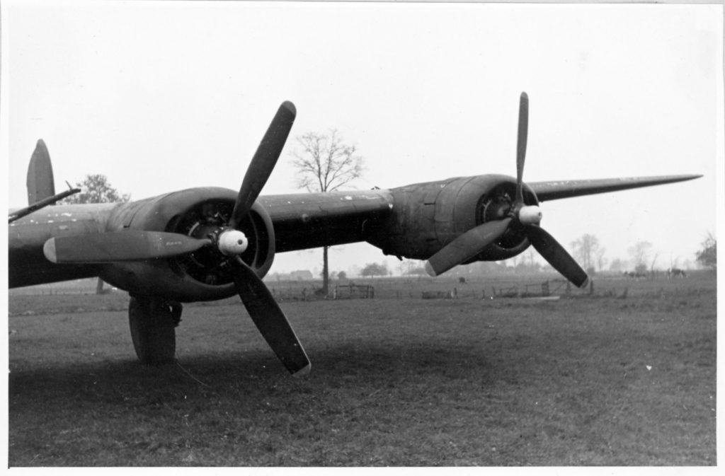
Bild 5     Linker Flügel mit Triebwerken.
Picture 5     Left wing with engines.

Bild 6     Blick über Waffenstand Rumpfoberseite, Antennenanordnung nach dem Leitwerk:
a) Rückspiegel für Schützen auf Rumpfoberseite
b) Revi N 6 A
Picture 6     View of the weapon stand [dorsal turret] top of the fuselage, antenna arrangement according to the control unit:
a) Rear-view mirror for gunner on fuselage top
b) Revi N 6A

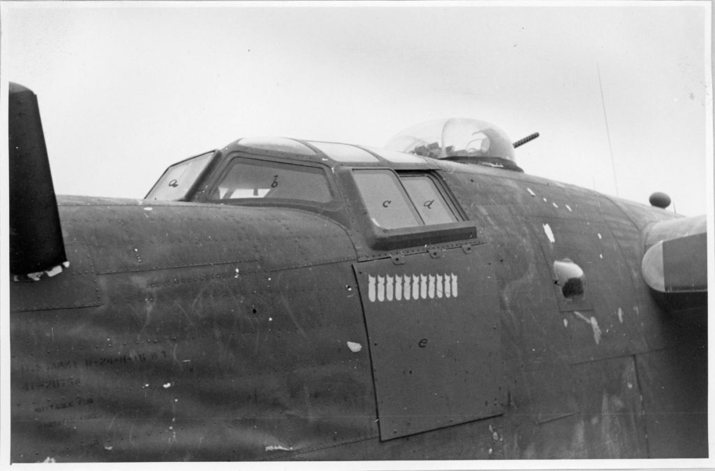
Bild 7     Blick auf Führerstand:
a), b), c), d), Panzerglasscheiben
e) Panzerplatte
Picture 7     View of pilot’s seat:
a), b), c), d), armored glass panes
e) Armor plate

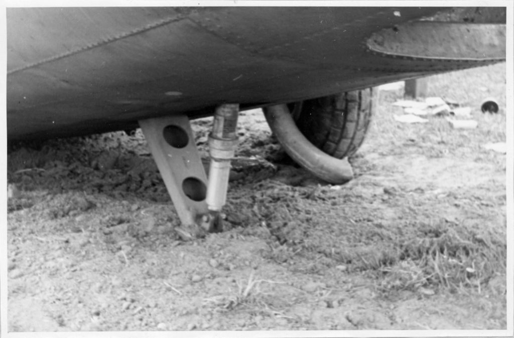
Bild 8     Ausgefahrener Notsporn
Picture 8     Extended emergency skid

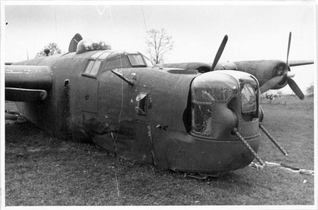
Bild 9     Bugturm mit Panzerglasscheibe und Antrieb.
Picture 9     Nose spire [sic] with armored glass pane and drive.

Bild 10     Plexiglasverkleidung des Bugturmes mit aufgemalter
a) Sprung des Plexiglasses wurde durch beidseitige Lochung der Plexiglashälften und durch Einziehen eines Drahtes zickzackförmig verbunden.
Picture 10     Plexiglass covering of the nose spire [sic] with painted [markings]
a) Crack of the plexiglass was zigzagged by bilateral perforation of the plexiglass halves and by pulling in a wire.

Bild 11     Blick in rückwärtigen Kabinenabschnitt mit MK-Kugel und Rumpfseitenständen.
Picture 11     View in the rear cabin section with machine-gun bullets and trunk sides.

Bild 12     Unterbringung der Munitionskästen für Heckstand an der rechten Bordwand hinter dem rechten Fenster.  Darüber Seenotsender mit Zubehöirbehälter.
a) Ausstiegklappe für Besatzung als auch Agenten und Sabotagebehältern.
Picture 12     Accommodation of the ammunition boxes for the rear deck on the right side of the vehicle
behind the right window.  Above that, distress transmitter with accessory container.
a) The exit flap for crew as well as agents and sabotage containers.

Bild 13     Blick auf ferngesteuerte FT-Geräte
a) BC – 966 – A
b) Stromversorgungsgerät für TR 5043
c) Modulator Unit BC – 456 – E
d) Radio Transmitter Unit BC – 433 – G
e) TR 5043
Picture 13     View of remote controlled FT devices
a) BC – 966 – A
b) Power device for TR 5043
c) Modulator unit BC – 456 – E
d) Radio transmitter unit BC – 433 – G
e) TR 5043

Bild 14     Die schwenkbaren Rumpfseitenwaffen mit Kreiskornvisier ohne Rücklaufbremse.
Picture 14     The swivel[ing] fuselage side weapons with a circular horn sight without a return brake.

Bild 15     Hydraulicbrett an der rechten Bordwand vor Heckstand.
Picture 15     Hydraulic board on the right side of the vehicle in front of the tail.

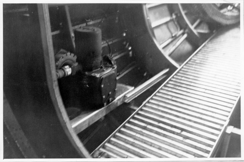
Bild 16     Servomotor für Seiten- und Höhenruder der Kurssteurerg A 5. Sitz des Gerätes in Flugrichtung hinter der Trennwand des Heckraumes.
Picture 16     Servomotor for side and height control of the steering wheel A 5.  Seat of the device in the direction of flight behind the partition of the rear compartment.

______________________________

THE PHOTOGRAPHS

Bild 1     Ansicht der Maschine von Vorn.

Picture 1     View of the machine from the front.

Comments: Note that none of the props appear to have been feathered, and the lower blades of two starboard props appear to be bent.  The landing gear has been lowered. 

______________________________

Bild 7     Blick auf Führerstand:
a), b), c), d), Panzerglasscheiben
e) Panzerplatte

Picture 7     View of pilot’s seat:
a), b), c), d), armored glass panes
e) Armor plate

Comments: The skin of the forward fuselage is crumpled.  Armored glass and pilot’s compartment exterior side armor – of obvious of interest to the photographer – are clearly visible.

______________________________

Bild 5     Linker Flügel mit Triebwerken.

Picture 5     Left wing with engines.

______________________________

Bild 4     Rumpfvorderteil:
a) Staurohr
b) Blister für Navigator beidseitig
c) Abtriftmesser
d) mit den Bewegungen der Waffen gekoppelte Panzerblickscheibe
e) Panzerplatten aussenbords, links und rechts

Picture 4     Fuselage front:
a) Pitot tube
b) Blisters for navigator on both sides
c) Drift [meter?]
d) Armored sighting window, coupled with the movement of the weapons
e) External armor plate, left and right

Comments: Note the attention to co-pilot’s exterior side armor, and crumpled skin of the front fuselage. 

______________________________


Bild 6     Blick über Waffenstand Rumpfoberseite, Antennenanordnung nach dem Leitwerk:
a) Rückspiegel für Schützen auf Rumpfoberseite
b) Revi N 6 A

Picture 6     View of the weapon stand [dorsal turret] top of the fuselage, antenna arrangement according to the control unit:
a) Rear-view mirror for gunner on fuselage top
b) Revi N 6A

Comments:  An excellent view of the top of the rear fuselage.  Note the furrows created by the impact of the starboard landing gear tire and fuselage bottom.  These extend only a very short distance behind the aircraft into the adjoining field, implying a very abrupt stop.  

The dorsal turret is probably the Martin A-3C version as opposed to A-3D, the latter of which commenced with Block H-25 Liberators.  Ironically, the German technical analyst referred to the turret gunsight as a “Revi N 6 A”.  (Revi?!) 

More intriguingly – at least, as described in the caption – are two circular rear-view mirrors mounted within opposite sides of the turret, each located between the .50 caliber machine gun and turret bubble.  The starboard inner turret mirror is also visible in photograph number 7.   

Notice that the cover of the starboard emergency life raft compartment has been detached from the fuselage.

______________________________
TO RELEASE & INFLATE LIFE RAFTS
PULL RELEASE HANDLE HARD

PULL RELEASE HANDLE AS FAR AS
POSSIBLE WHICH RELEASES DOORS

PULL INSIDE RELEASE HANDLE…

Comments: This is an 800 dpi scan from the previous photo, showing instructions concerning release of the B-24’s life-rafts.

______________________________
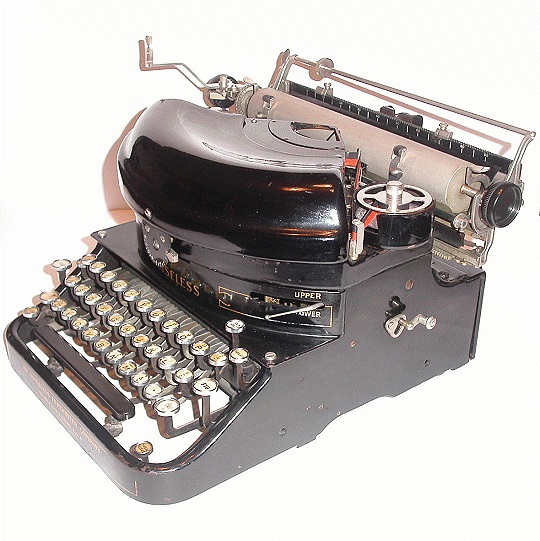
Bild 10     Plexiglasverkleidung des Bugturmes mit aufgemalter
a) Sprung des Plexiglasses wurde durch beidseitige Lochung der Plexiglashälften und durch Einziehen eines Drahtes zickzackförmig verbunden.

Picture 10     Plexiglass covering of the nose spire [sic] with painted [markings]
a) Crack of the plexiglass was zigzagged by bilateral perforation of the plexiglass halves and by pulling in a wire.

Comments: Here’s a different way of looking at things: The photographer stood atop the front fuselage of Tell Me More, and pointing his camera down, photographed the top of the “dome” of the Emerson A-15 nose turret.  Immediately apparent are numbers denoting the rotational azimuth of the turret – in gradations of 15 degrees relative to the fuselage center line – engraved or etched into the plexiglass.  The overwhelming majority of photographs of the Emerson A-15 turret, where the turret is seen from the side, naturally don’t show this feature. 

(Did the turret dome of the CAC / Motor Products tail turret have a similar azimuth scale?)

______________________________
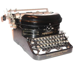
Bild 9     Bugturm mit Panzerglasscheibe und Antrieb.

Picture 9     Nose spire [sic] with armored glass pane and drive.

Comments: Another view of the A-15 turret.  Immediately apparent are the pane of armored glass and elevation drives for the guns.  There’s a small mystery here:  How was the turret dome shattered?  Flak?  Fighters?  During the plane’s landing?

______________________________

Comments: An excellent side view of an Emerson A-15 turret, albeit not from the KU Report.  Instead, from Air Force Photo 53584AC / A12599.  This picture illustrates an interesting aspect of the general design of the A-15, as opposed to the structure of dorsal aircraft turrets:  The guns are located well below the gunner’s head and torso.

Caption: “ENGLAND – S/Sgt. Edward J. Mickey, a B-24 nose turret gunner, of Kingston, Pa., has 30 missions to his credit and holds the Distinguished Flying Cross and the Air Medal with 3 Oak Leaf Clusters. (53584AC / A12599)”

Here’s an interesting video (at the website of Hugh Fenlon) of an Emerson A-15 in operation, albeit not (!) in a B-24.

______________________________

Bild 11     Blick in rückwärtigen Kabinenabschnitt mit MK-Kugel und Rumpfseitenständen.

Picture 11     View in the rear cabin section with machine-gun bullets and [trunk] sides

Comments:  Fuselage interior, looking forward.  This image provides an excellent view of the waist gun opening covers in their stowed positions, and, the location of oxygen bottles.  The wind blast deflector for the port gun can be seen just ahead of the open waist window.  These are the original “open” style B-24 waist gun positions that are neither staggered nor enclosed.  According to Alan Blue’s book, that modification only commenced with Block H-20 Liberators. 

______________________________

Bild 13     Blick auf ferngesteuerte FT-Geräte
a) BC – 966 – A
b) Stromversorgungsgerät für TR 5043
c) Modulator Unit BC – 456 – E
d) Radio Transmitter Unit BC – 433 – G
e) TR 5043

Picture 13     View of remote controlled FT devices
a) BC – 966 – A
b) Power device for TR 5043
c) Modulator unit BC – 456 – E
d) Radio transmitter unit BC – 433 – G
e) TR 504

______________________________

Bild 14     Die schwenkbaren Rumpfseitenwaffen mit Kreiskornvisier ohne Rücklaufbremse.

Picture 14     The swivel[ing] fuselage side weapons with a circular horn sight without a return brake.

Comments:  The simple circular ring-and-bead gunsight mounted atop the waist machine guns.

______________________________

Bild 12     Unterbringung der Munitionskästen für Heckstand an der rechten Bordwand hinter dem rechten Fenster.  Darüber Seenotsender mit Zubehöirbehälter.
a) Ausstiegklappe für Besatzung als auch Agenten und Sabotagebehältern.

Picture 12     Accommodation of the ammunition boxes for the rear deck on the right side of the vehicle behind the right window.  Above that, distress transmitter with accessory container.
a) The exit flap for crew as well as agents and sabotage containers.

Comments:  Tail turret ammunition storage box, and ventral entry / escape hatch in open (stowed) position. 

______________________________
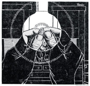
Bild 15     Hydraulicbrett an der rechten Bordwand vor Heckstand.

Picture 15     Hydraulic board on the right side of the vehicle in front of the tail.

______________________________
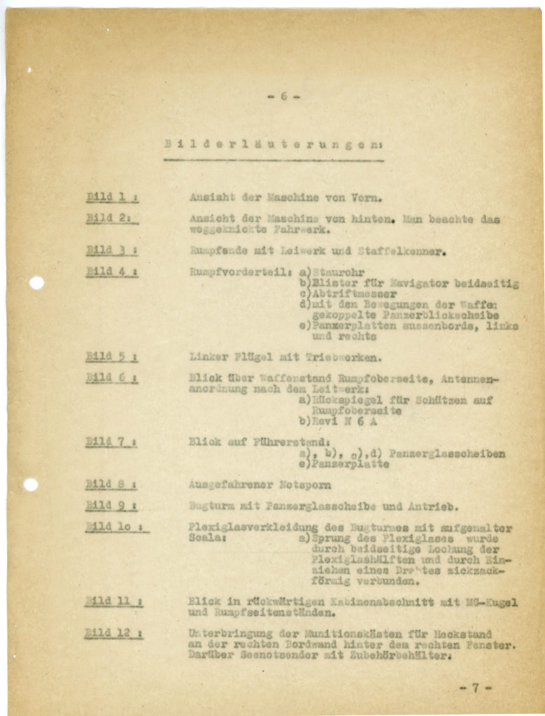
Bild 16     Servomotor für Seiten- und Höhenruder der Kurssteurerg A 5. Sitz des Gerätes in Flugrichtung hinter der Trennwand des Heckraumes.

Picture 16     Servomotor for side and height control of the steering wheel A 5.  Seat of the device in the direction of flight behind the partition of the rear compartment.

______________________________
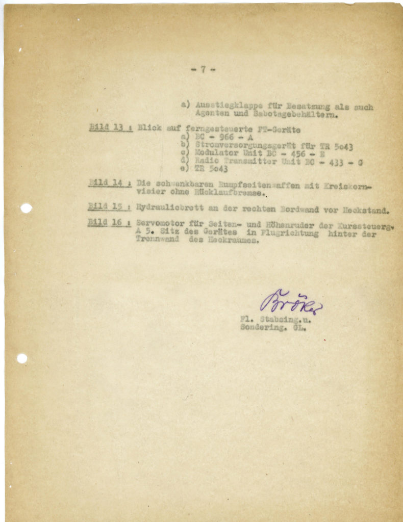
Bild 8     Ausgefahrener Notsporn

Picture 8     Extended emergency skid

______________________________
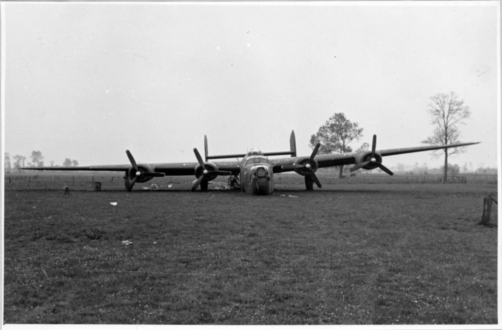
Bild 2     Ansicht der Maschine von hinten.  Man beachte das weggeknickte Fahrwerk.

Picture 2     View of the machine from behind. Note the bent landing gear.

Bild 3     Rumpfende mit Leiwerk und Staffelkenner.

Picture 3     Fuselage tail with body work and [squadron signal light].

______________________________
There ends the tail – literally (ahem! – pardon the pun!), and figuratively – of Tell Me More.  The photos tell the story of a single B-24 Liberator – of very, very many – that was lost in the air war against Germany in the Second World War. 

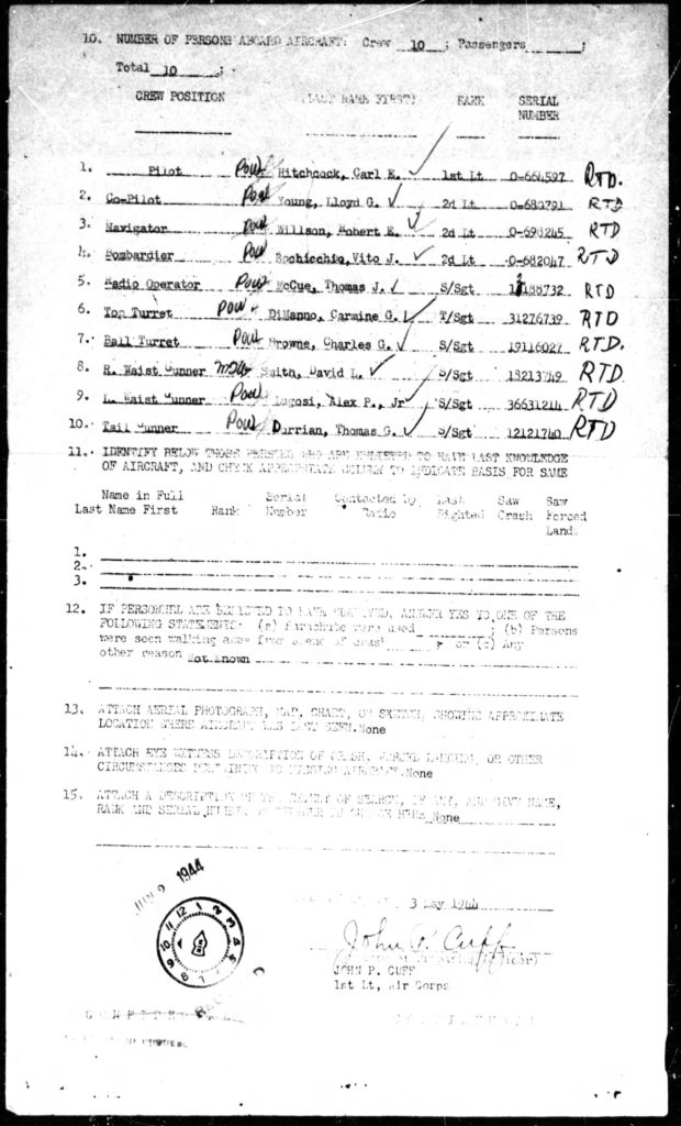
Certainly every man in the plane’s crew certainly had his own, much more human story, as well:  Of attempted evasion, eventual capture, and ultimately liberation and freedom.  I have no way of knowing if in the decades since 1945 those stories were recorded and preserved – especially as suggested by the inscription on the tombstone of Lt. Robert Willson – but it would be nice to think they have been. 

So, let this collection of photos stand as a symbol of a past that should not be forgotten.

______________________________
References

The B-24 Liberator

Birdsall, Steve, B-24 Liberator in Action (Aircraft No. 21), (Illustrated by Don Greer), Squadron/Signal Publications, Inc., Carrollton, Tx., 1975

Blue, Allan G., The B-24 Liberator – A Pictorial History, Charles Scribner’s Sons, New York, N.Y., 1975

Davis, Larry  B-24 Liberator in Action (Aircraft No. 80), (Illustrated by Perry Manley), Squadron/Signal Publications, Inc., Carrollton, Tx., 1987

Joe Baugher’s list of B-24 serial numbers, at JoeBaugher.com

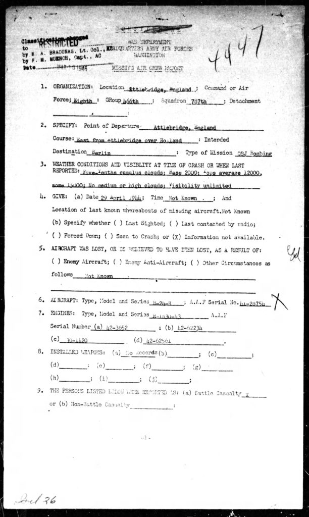
B-24H 41-28754

American Air Museum in England

8th Air Force Historical Society

Luftgaukommando Report KU 1680

United States National Archives – Collection of Foreign Record Seized – Record Group 242: “Records of Luftgaukommandos: German Reports of Downed Allied Fighters and Other Aircraft – KU Reports”

Report KU 1680 at NARA: (In) Records Group 242, Entry 1022, Shelf Location 190 / 14 / 9-12 / 1-5, Box 231

Demonstration of Emerson A-15 Turret

Hugh Fenlon’s website

Modelling the B-24H Liberator

US-Aircraft.com History-Modelling-Forum

IPMS USA

Captive Technology: German Photographs of Electronic Equipment in a Downed Special Operations Squadron B-24 Liberator – III

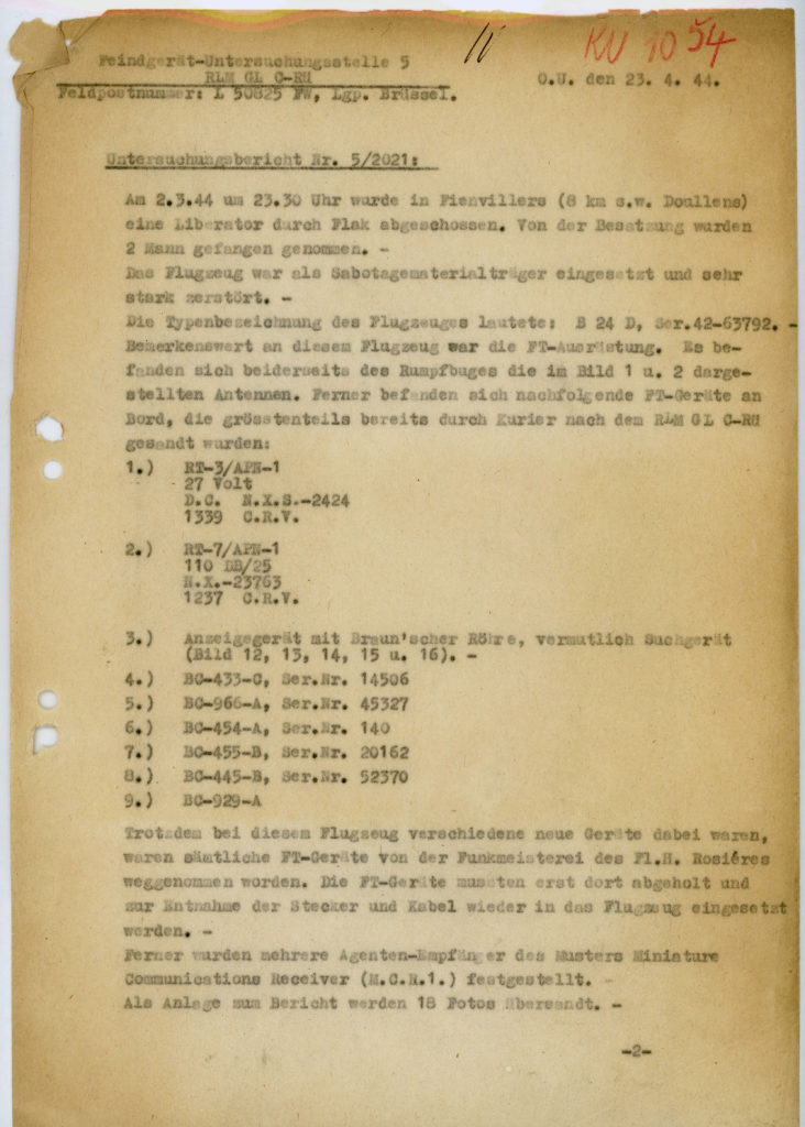
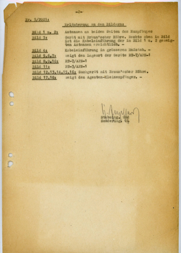
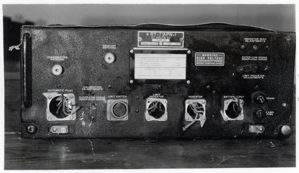
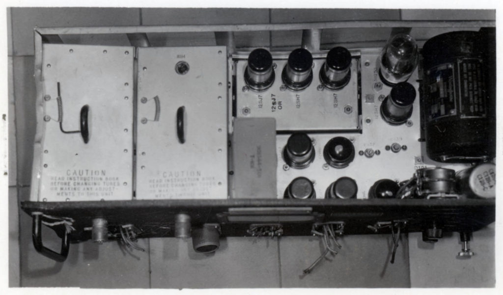
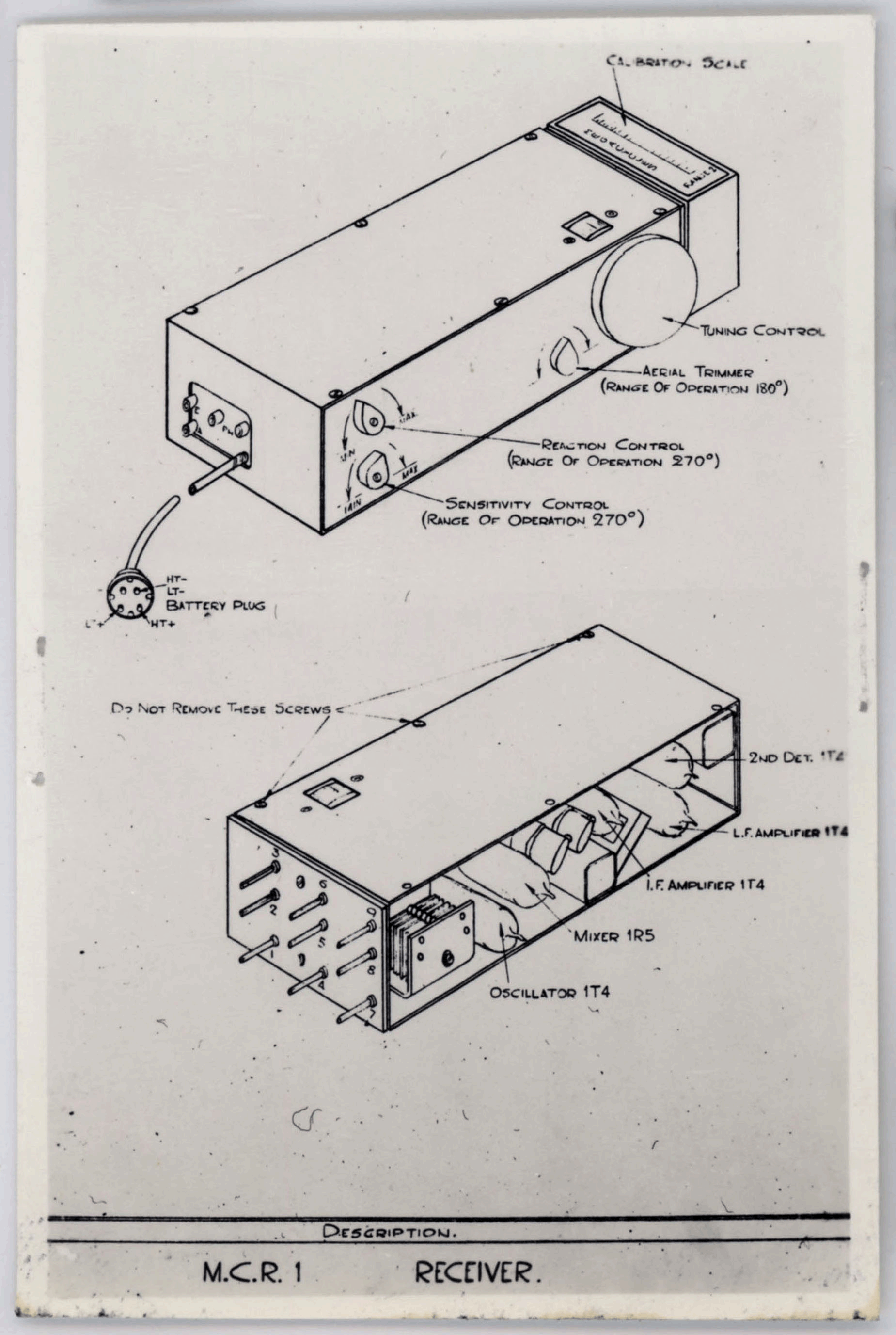
This page presents the other pictures in Luftgaukommando Report 1054, in a format akin to the prior blog post.

____________________ 
DESCRIPTION OF AIRCRAFT 42-63792, AND PHOTO CAPTIONS

Feindgerät-Untersuchungsstelle 5
RLM GL C-Rü                                                                                                O.U. den 23.4.44
Feldpostnummer: L 50825 FW, Lgp. Brüssel.

Untersuchungsbericht Nr. 5/2021:

Am. 2.3.44 um 23.30 Uhr wurde in Fienvillers (8 km s.w. Doullens) eine Liberator durch Flak abgeschossen.  Von der Besatzung wurden 2 Mann gefangen genommen.

Das Flugzeug war als Sabotagematerialträger eingesetzt und sehr stark zerstört.

Die Typenbezeichnung des Flugzeuges lautete: B 24 D, Ser. 42-63792.  Bemerkenswert an diesem Flugzeug war die FT-Ausrüstung.  Es befanden sich beiderseits des Rumpfbuges die im Bild 1 u. 2 dargestellten Antennen.  Ferner befanden such nachfolgende FT-Geräte an Bord, die grösstenteils bereits durch Kurier nach dem RLM GL C-Rü gesandt wurden:

1.     RT-3 / APN-1
27 Volt
D.C. N.X.S. – 2424
1341 C.R.V.

2.    T-7 / APN-1
110 DB / 25
N.X. – 23763
1237 C.R.V.

3.    Anzeigegerät mit Braun’scher Röhre, vermutlich Suchgerät (Bild 12, 13, 14, 15 u. 16). –
4.    BC-433-C, Ser. Nr. 14506
5.    BC-966-A, Ser. Nr. 45327
6.    BC-454-A, Ser. Nr. 140
7.    BC-455-B, Ser. Nr. 20162
8.    BC-445-B, Ser. Nr. 52370
9.    BC-929-A

Trotzdem bei diesem Flugzeug verschiedene neue Geräte dabiei waren, waren sämtliche FT-Geräte von der Funkmeisterei des Fl.H. Rosiéres weggenommen worden.  Die FT-Geräte mussten erst dort abgeholt und zur Entnahme der Stecker und Kabel wieder in das Flugzeug eingesetzt werden. –

Ferner wurden mehrere Agenten-Empfänger des Musters Miniature Communications Receiver (M.C.R.1.) festgestellt.

Als Anlage zum Bericht werden 18 Fotos übersandt.

Erläutering zu den Bildern:

Bild 1 u. 2:     Antennen an beiden Seiten des Rumpfbuges
Bild 3:           Gerät mit Braun’scher Röhre.  Rechte oben im Bild ist die Kabeleinführung der im Bild 1 u. 2 gezeigten Antennen ersichtlich.
Bild 4:          Kabeleinführung in grösserem Masstab.
Bild 5, 6, 7:  zeigt den Lageert der Geräte RT-7 / APN-1
Bild 8, 9, 10: RT-7 / APN-1
Bild 11:         RT-3 / APN-1
Bild 12, 13, 14, 15, 16: Suchgerät mit Braun’scher Röhre.
Bild 17, 18:   zeigt den Agenten-Kleinempfänger.

Engelhard
Stabsing. Und
Sondering. GL

____________________
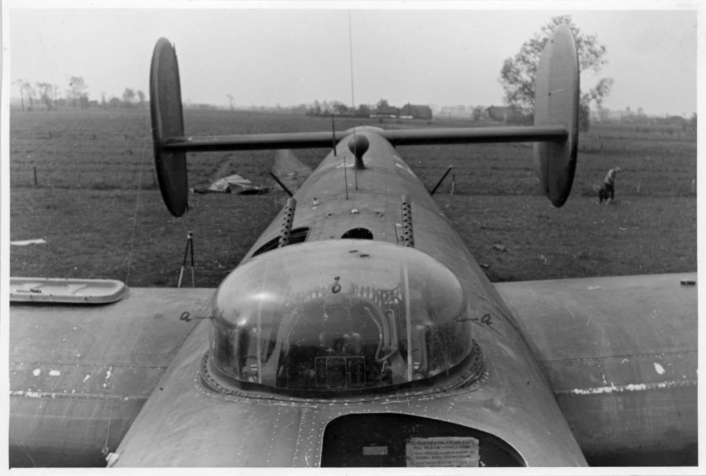
Enemy equipment investigation center 5                                             KU 1154
Ministry of the Air Force GL C-Rue                  Local Quarters, 23 April 1944
Field postal No L 50825 FW
Air District Post Office Brussels

Investigation Report No 5 / 2021

On 2 March 1944 at 2330 a Liberator had been shot down by anti-aircraft over Fienvillers (8 km southwest of Doullens).  Two members of the crew had been captured.  The plane was equipped as sabotage material-carrier and therefore very seriously damaged.

The type markings of the plane were as follows: B 24 D, Serial No. 42-63792.  This plane was equipped with remarkable radio equipment.  There were aerials on both sides of the front of the fuselage as pictures 1 and 2 show.  Further, there was the following radio equipment on board, the greatest part of which has been sent by messenger to the Ministry of the Air Dorces GL C-Rue.

1.     RT-3 / APN-1
27 Volt
D.C. N.X.S. – 2424
1341 C.R.V.

2.    RT-7 / APN-1
110 DB / 25
N.X. – 23763
1237 C.R.V.

3.    Indicator-set with Bruan’scher tube, probably search-equipment (see picture 12, 13, 14, 15 and 16)
4.    BC-433-C, Ser. No. 14506
5.    BC-966-A, Ser. No. 45327
6.    BC-454-A, Ser. No. 140
7.    BC-455-B, Ser. No. 20162
8.    BC-445-B, Ser. No. 52370
9.    BC-929-A

Though this plane was equipped with different kinds of new radio equipment, all radio equipment had been taken out by the radio office of the Air-base Rosieres.  The radio equipment had to be obtained from that office, and for the purpose of the removal of the plugs and cables had to be installed again into the plane.  Also, several agent receivers of the type “Miniature Communications Receiver (M.C.R. 1)” were found.

Enclosed in this report 18 photographs.

Photo explanation.

Picture 1 and 2:     Antenna on both sides of the front of the fuselage.
3:     Equipment with Bruan’scher tube.  In the right upper corner of the picture the cable installation of the antenna (shown in picture 1 and 2) can be seen.
4:     Cable installation on larger scale.
5, 6, 7:     shows the location of the equipment RT-7 / APN-1
8, 9, 10:   RT-7 / APN-1
11:            RT-3 / APN-1
12, 13, 14, 15, and 16     Search equipment with Braun’scher tube.
17 and 18:     Shows the Miniature-Communications-Receiver.

Enclosures:

Instructions for the
“Miniature Communications Receiver”
and 18 photographs.

Signed: Engelhard
Staff-Engineer and Special Engineer

____________________

PHOTOS: APN-1 Radar Altimeter and M.C.R.-1 Miniature Communications Receiver

____________________
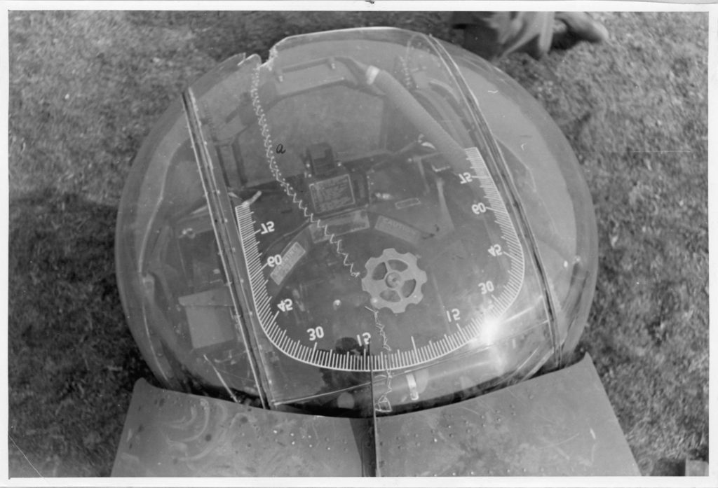
Bild 8, 9, 10: RT-7 / APN-1

Pictures 8, 9, 10:   RT-7 / APN-1

Bild 8, 9, 10: RT-7 / APN-1

Pictures 8, 9, 10:   RT-7 / APN-1

Bild 8, 9, 10: RT-7 / APN-1

Pictures 8, 9, 10:   RT-7 / APN-1

Bild 11:         RT-3 / APN-1

Picture 11:            RT-3 / APN-1

Comments:  Here are several views of the APN-1 radar altimeter.  The case has been damaged and the front cable sockets removed, but the interior of the unit – chassis and attached components – is completely intact. 

A video description of the APN-1, created by the infoagemuseum (Wall, New Jersey – in Monmouth County) and narrated by Mr. Ray Chase, describes the operation of the unit.  A beautiful set of illustrations of a (quite intact!) APN-1 is available at the website of Aces, Contrails and Unsung Heroes, while the schematic diagram of the APN-1 can be found at this link to the Waverley Amateur Radio Society

____________________
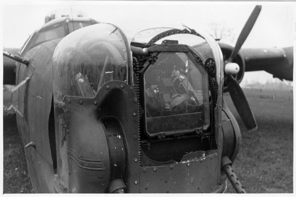
Bild 17, 18:   zeigt den Agenten-Kleinempfänger.

Pictures 17 and 18:     Shows the Miniature-Communications-Receiver.

Bild 17, 18:   zeigt den Agenten-Kleinempfänger.

Pictures 17 and 18:     Shows the Miniature-Communications-Receiver.

Bild 17, 18:   zeigt den Agenten-Kleinempfänger.

Pictures 17 and 18:     Shows the Miniature-Communications-Receiver.

Comments for Photos 17 and 18: One aspect of the crew’s intended mission is evidenced by the subject of these images:  A Miniature Communications Receiver – 1 (“M.C.R.-1”).  The M.C.R.-1, a portable, tube-based miniature receiver unit, was designed for use by S.O.E. (Special Operations Executive) Agents, Special Forces, and Resistance Groups.    

An M.C.R.-1 unit with its associated components is seen lying on a table.  Three power packs (one of which is connected to the unit by a short cable) are present, while on the right are three “Frequency Plug-In” coil packs, each of a different frequency range (2.5 MHz – 4.5 MHz, 4.5 MHz – 8 MHz, and 8 MHz – 15 MHz), which extend the receiver’s length. 

A thorough description of the M.C.R.-1 (with very nice color photographs) is available at the CryptoMuseum website.  The operating manual for the receiver – in which it’s dubbed a “Midget Communications Receiver” – can be found here, while the schematic diagram of the unit (via the Waverley Amateur Radio Society) can be found here

The Luftgaukommando Report includes a small and fascinating bonus:  It contains a very actual – quite original – very genuine – surviving remnant of the McDonald crew’s last mission: a placard of operating instructions for an M.C.R.-1. 

A superb set of images of an M.C.R.-1 and its associated components (including interior views of both the receiver and its power supply) as well as instructions covering its installation and use, is available at Jan Poortman’s PA3ESY Vintage Radio Collection website

____________________
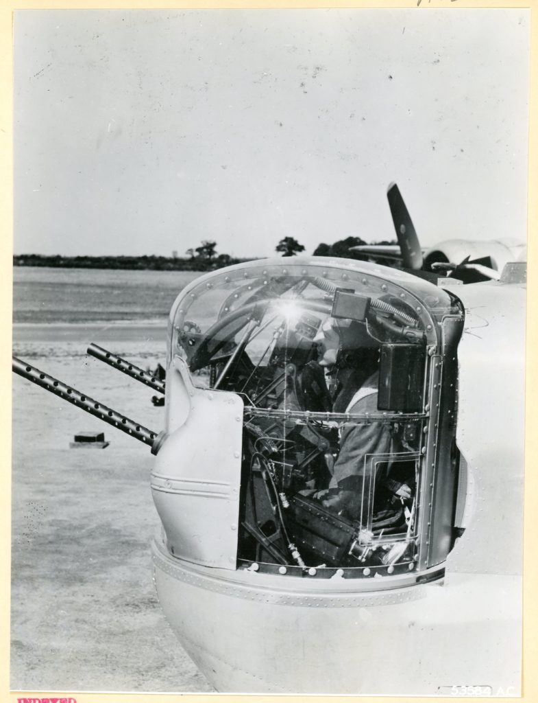
References

Harrington Museum – Carpetbagger Planes (compiled by Roy Tebbutt)

Harrington Museum  (Aircraft of the 801st / 492nd Bomb Groups, and 406th NLS, compiled by Roy Tebbutt)

Harrington Museum (List of Allied Aircraft lost on Special Duty Operations, compiled by Roy Tebbutt)

Frank G. McDonald Crew

USAAF Special Operations – 801 BG – 492 BG Carpetbaggers (McDonald Crew History)

USAAF Special Operations – 801 BG – 492 BG Carpetbaggers (McDonald Crew Orders)

USAAF Special Operations – 801 BG – 492 BG Carpetbaggers (McDonald Mission Reports – zip file)

Escape & Evasion Report 669 (Lt. Frederick C. Kelly)

NARA Escape & Evasion Report search portal

NARA Escape & Evasion Report search portal (Escape & Evasion Report 669, for Frederick C. Kelly)

WW II Escape and Evasion Information Exchange (Directory of MIS-X Report Numbers for members of US Army Air Forces, and, US Army Ground Forces) – An extraordinarily comprehensive website! 

BC-929A “Rebecca” Radar Interrogator

Smithsonian National Air and Space Museum (general description)

AeroAntique.com (general description of BC-929A “Rebecca” Radar Interrogator)

QSL.net (“Connecting Hams Around the World”) (brief description)

Wikipedia Entry for Rebecca Radar Interrogator

Walt Gromov’s Radio Museum – Communications in WW I and WW II:
Graphic Survey of Radio and Radar Equipment Used by the Army Air Forces – Radio Navigation Equipment – 1 July 1945” (BC-929 and APN-1 illustrated in document)

Braun’scher Tube

The Inventors.org

APN-1 Radar Altimeter

Waverley Amateur Radio Society

Waverley Amateur Radio Society (APN-1 schematic diagram (this ain’t no Heathkit!))

HyperWar (Use of the APN-1)

Inforagemuseum (Video about APN-1)

VMARS (Vintage and Military Amateur Radio Society) Manuals (APN-1 Manual
Handbook Maintenance Instructions for Radio Set AN / APN-2  –  AN APN-2Y  –  AN / APN-2B (1945 09 25) (Technical Order 12P-5 – 2APN-2“)

Miniature Communications Receiver M.C.R.-1

Crypto Museum (Description of M.C.R.-1)

Crypto Museum (Detailed instruction manual for M.C.R.-1)

Imperial War Museum (Photographs of M.C.R.-1)

Waverley Amateur Radio Society (M.C.R.-1 schematic diagram)

Jan Poortman’s Vintage Radio Website (Illustrations of M.C.R.-1)

A Book…

Freeman, Roger, The Mighty Eighth – A History of the U.S. 8th Army Air Force, Doubleday and Company, Inc., Garden City, N.Y., 1970 (Special Operations Group – Carpetbagger history summarized on p. 263)

A B-24 Liberator, Up Close and Personal: German Photographs of a Downed B-24 in Holland – I

In September of 2016, this blog commenced with a post about Luftgaukommando Reports – documents created by the Germans to record information about aircraft and aircrews of the United States and British Commonwealth air forces shot down over German-occupied Europe and Germany itself, during the Second World War.  Also known as KU (Kampflugzeug Unterlagen – “Downed Allied Aircraft”) Reports, these documents are part of Records Group 242 (Collection of Foreign Records Seized, 1675-1983) in the United States National Archives. 

By nature, Luftgaukommando Reports comprise records compiled by the Germans, and not uncommonly, include documents (personal and otherwise) and other items, such as V-Mail and hand-written correspondence, carried or worn (dog tags) by air crewmen. 

That “first” post (a multitude of keystrokes ago…!) focused on Luftgaukommando Report J 2525, which covers “Chicago’s Own”, a P-51D Mustang (44-41010) of the 353rd Fighter Squadron of the 354th Fighter Group, which was piloted by Captain Gordon T. McEachron, and served to introduce and describe general aspects of Luftgaukommando Reports. 

What makes Luftgaukommando Report J 2525 noteworthy is the presence of several excellent photographs of the downed and mostly intact – albeit no longer quite flyable! – Mustang. 

Report J2525 is one of the very few Luftgaukommando Reports containing photographs.  Sometimes, like the pictures of Chicago’s Own, such images suggest the features, components, and design aspects of American warplanes that particularly drew the attention of German investigators and technical analysts.

In a large sense, perhaps an apt word for such images is “evocative”.  It’s one thing to read “about” the loss of an American military plane in a book, article, or Missing Air Crew Report.  It’s quite another to actually see and hold an image of what that aircraft looked like, to those who actually flew within it over seven decades ago. 

____________________
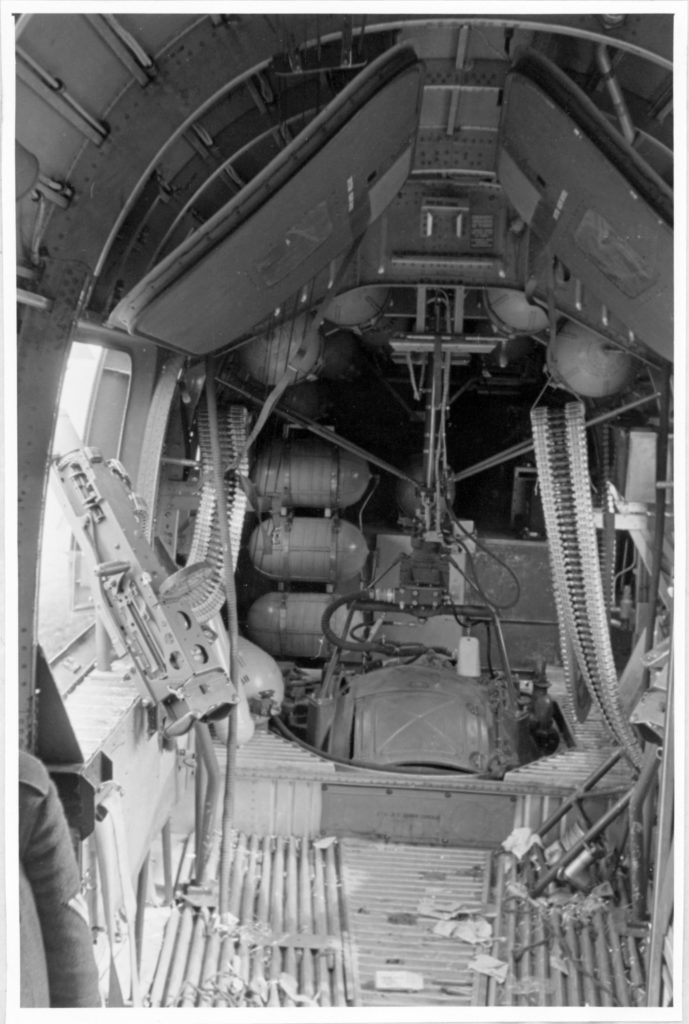
This post presents another series of German photographs of a downed American warplane:  An entirely intact yet rather broken 8th Air Force B-24 Liberator – ironically nicknamed “Tell Me More” – which was examined by the Germans after force-landing in Holland on April 29, 1944.  The 15 images presented here, in Luftgaukommando Report KU 1679, represent the second highest total quantity of images found in any of the Luftgaukommando Reports (whether J, KU, or ME Reports) I’ve thus far examined.  (The largest quantity of photographs in a Luftgaukommando Report– 19 – hopefully the subject of a future post!)

“Tell Me More”, a B-24H 41-28754 of the 787th Bomb Squadron, 466th Bomb Group, 8th Air Force, squadron code 6L * N, was piloted by 1 Lt. Carl E. Hitchcock, and was lost during the Group’s mission to Berlin on April 29, 1944.  Its loss is covered in MACR 4447.  The 466th lost one other Liberator that day (41-29399, “T9 * D”, of the 784th Bomb Squadron, covered in KU 1681) while the 8th Air Force lost 61 other B-17s and B-24s; the 15th Air Force 4 B-24s. 

In human costs, approximately six hundred and seventy men.

According to tables of B-24 Liberator serial numbers in Allan Blue’s The B-24 Liberator (pp. 195 and 202), Tell Me More was a B-24H-1DT, and – going by serial numbers alone, rather than calendar date of manufacture and delivery – was the very first ”H” version of all 3,100 B-24H Liberators manufactured. 

The crew list from the MACR is shown below:

____________________
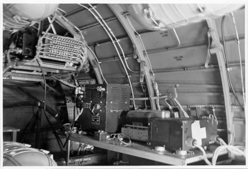
Neither the MACR nor the KU Report contain information describing the actual cause of the aircraft’s loss.  The KU Report simply states that the plane, “made an emergency landing 6 km east of Apeldoorn”, also vaguely mentioning “Liberator Shot Down”.  Regardless, as can be seen from the list in the MACR and KU Report, the entire crew of 10 was eventually captured.  

Fortunately, all survived the war. 

They were:

PilotHitchcock, Carl Edward, 1 Lt., 0-664597
Mrs. Mary Hitchcock (mother), North Bradley St., McKinney, Tx.
Born 1/17/15, Tx.; Died 9/23/95
Buried Sunset Memorial Park, San Antonio, Tx.
POW Stalag 7A (Moosburg)
Captured by 6/22/44

Co-PilotYoung, Lloyd G., 2 Lt., 0-680791
Mrs. Mary Young (mother), Park View Ave., Knoxville, Tn.
Born 9/25/18, Smith County, Tn.
POW Stalag Luft 3 (Sagan)
Captured May 3, 1944, at Vorort v Tiel, by Officer Heitzwebel

NavigatorWillson, Robert Edwin, 2 Lt., 0-698245
Mrs. Frances (Gardner) Willson (wife), 3026 Lebanon, El Paso, Tx.
Born 9/9/20, Sherman, Tx.; Died 2/3/08
Buried Dallas – Fort Worth National Cemetery, Dallas, Tx.
On tombstone – “Ex-POW – It is well with my soul.”
POW – Camp Unknown
Captured by 6/22/44

Robert Willson’s tombstone, photographed by FindAGrave contributor William Nance, is shown below:

BombardierBochicchio, Vito Joseph, 2 Lt., 0-682047
Mrs. Margaret Bochicchio (mother), West 21st St., New York, N.Y.
Born 1/1/17, New York, N.Y.; Died 3/23/10
Buried Calverton National Cemetery, Calverton, N.Y.
POW Stalag Luft 3 (Sagan)
Captured May 3, 1944, at Vorort v Tiel, by Officer Heitzwebel

Flight Engineer DiManno, Carmine Gerard, T/Sgt., 31276739
Mrs. Mary Dimanno (mother), 19 Orchard St., Hartford, Ct.
Born 7/7/23; Died 5/29/77
Buried East Cemetery, Manchester, Ct.
POW Stalag Luft 4 (Gross-Tychow)
Probably Captured April 29, 1944, near Apeldoorn

Radio OperatorMcCue, Thomas J. (“Thomas Francis”?), S/Sgt., 12188732
Mrs. Lee V. McCue (mother), 476 Dean St., Brooklyn, N.Y.
POW Stalag Luft 4 (Gross-Tychow)
Captured April 29, 1944, near Apeldoorn

Gunner (Ball Turret)Browne, Charles Graham, S/Sgt., 19116027
Mrs. Agnes G. Browne (mother), East South Mariposa St., Glendale, Ca.
Born 12/21/19, Twin Falls, Id.
POW Stalag Luft 3 (Sagan)
Captured April 29, 1944, near Apeldoorn

Gunner (Right Waist)Smith, David Leon, S/Sgt., 18213749
Mrs. Mary Smith (mother), General Delivery, New Franklin, Mo.
POW Stalag Luft 1 (Barth)
Captured by January 5, 1945

Gunner (Left Waist)Lugosi, Alex Paul, S/Sgt., 36631214
Mrs. Anna Lugosi (mother), 12632 Wallace St., Chicago, Il.
Born 11/11/21, Chicago, Il.
POW – Camp Unknown (numerical indicator is “0”)
Captured April 29, 1944, near Apeldoorn

Gunner (Tail)Dorrian, Thomas George, S/Sgt., 12121740
Mr. James Dorrian (father), 2541 99th St., East Elmhurst, Long Island, N.Y.
Born New York, N.Y.
POW Stalag Luft 3 (Sagan)
Captured April 29, 1944, near Apeldoorn

____________________
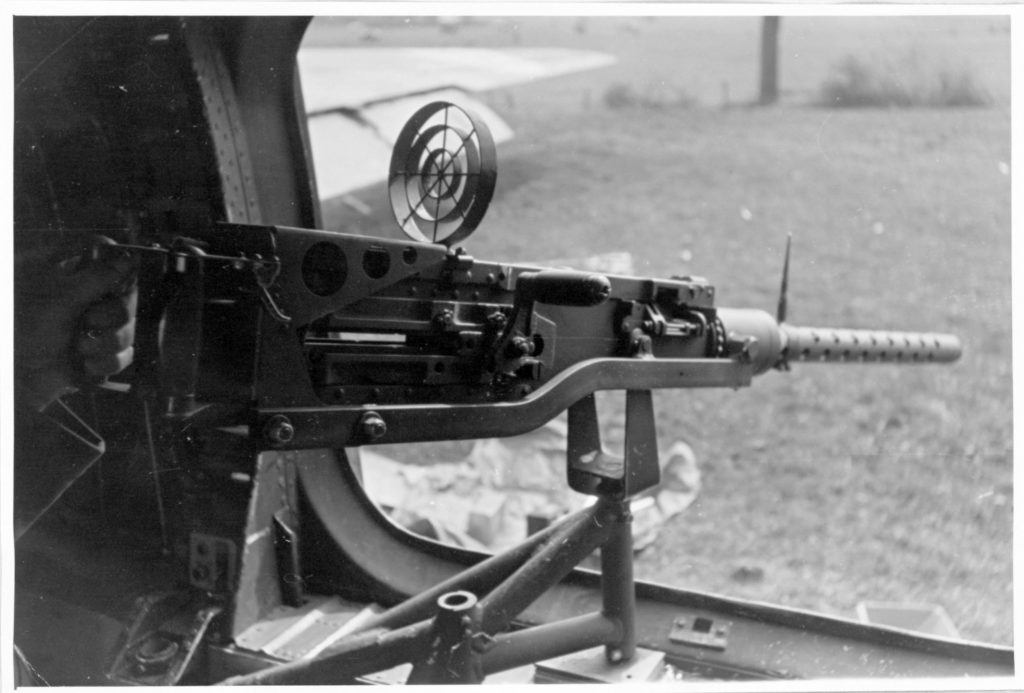
The crew list and other documents in the KU Report imply that the crew split up after landing – the enlisted men in one group, and the four officers in two pairs – in an attempt to evade capture.  This is suggested by their dates of capture, which are listed in the KU Report as follows:

Captured on April 29, at Apeldoorn:

T/Sgt. Carmine G. DiManno (flight engineer)
S/Sgt. Thomas J. McCue (Radio Operator)
S/Sgt. Charles G. Browne (Ball Turret Gunner)
S/Sgt. Alex P. Lugosi (Left Waist Gunner)
S/Sgt. Thomas G. Dorrian (Tail Gunner)

Captured May 3, at “Vorort v Tiel”, by an “Officer Heitzwebel”:

2 Lt. Lloyd G. Young (Co-Pilot)
2 Lt. Vito J. Bochicchio (Bombardier)

Captured by June 22, at an unspecified location:

1 Lt. Carl E. Hitchcock (Pilot)
2 Lt. Robert E. Willson (Navigator)

Managed to evade until early January, 1945; location of capture unspecified:

S/Sgt. David L. Smith (Right Waist Gunner)

____________________
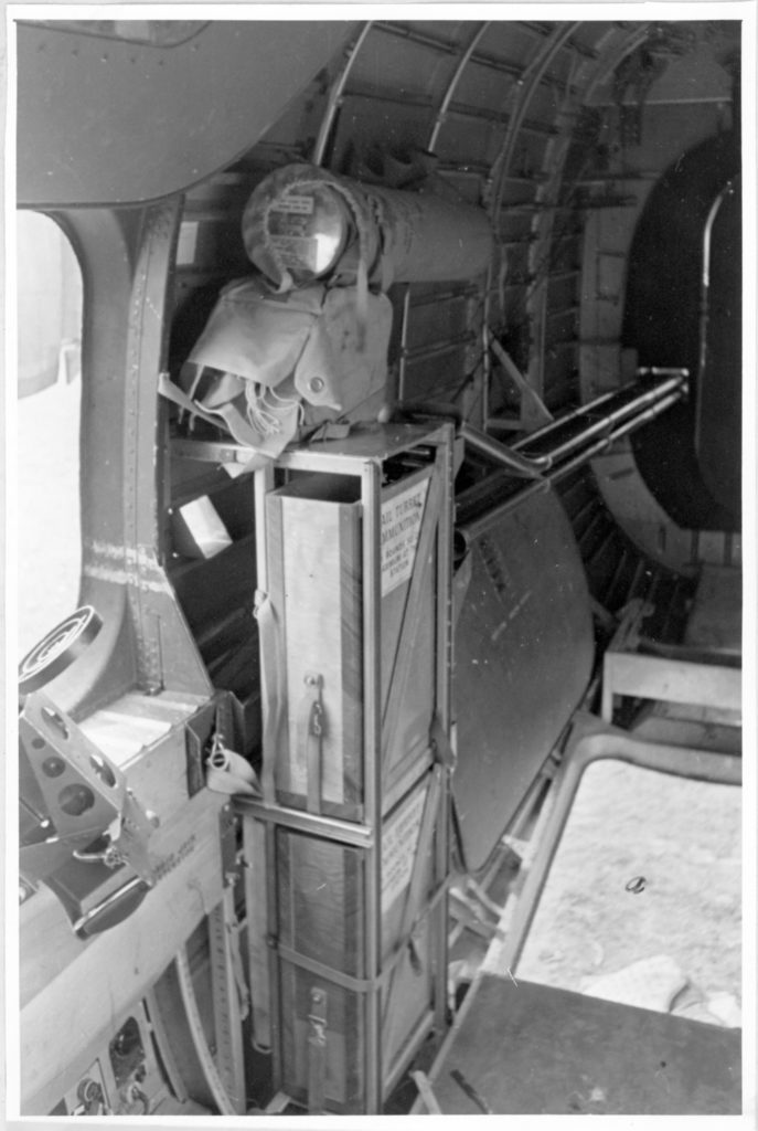
The specific location of the aircraft’s landing is presented as follows:

1) The American Air Museum website lists the plane as having crash-landed at Apeldoorn.

2) The Eighth Air Force Historical Society lists the plane as having landed at Wilp-Achterhoek, in Gelderland.

3) The KU Report gives two locations for the plane’s loss:

a) 6 kilometers east of Apeldoorn
b) 4 kilometers south of Touge

Touge is east-northeast, and Wilp-Achterhoek directly east, of the geographic center of Apeldoorn.  Based on this information, I’ve created three Oogle maps at successively larger scales, “zooming in” on the location which seems (seems!) to be the best composite of the above-reported locations.  This is denoted by the north-south oriented red ovals superimposed on the map, just southwest of Wilp-Achterhoek, and repeated on the Google Earth view of the same locale. 

These maps and the aerial photograph are presented below:

Here is an image of Tell Me More from the American Air Museum website, showing the relatively intact and rather bent B-24 resting on its forward fuselage, on a vacant field.  The American Air Museum website includes two other images of the plane, one showing what seems to have been a very hastily applied individual aircraft letter – “N” – on the lower port fin. 

____________________
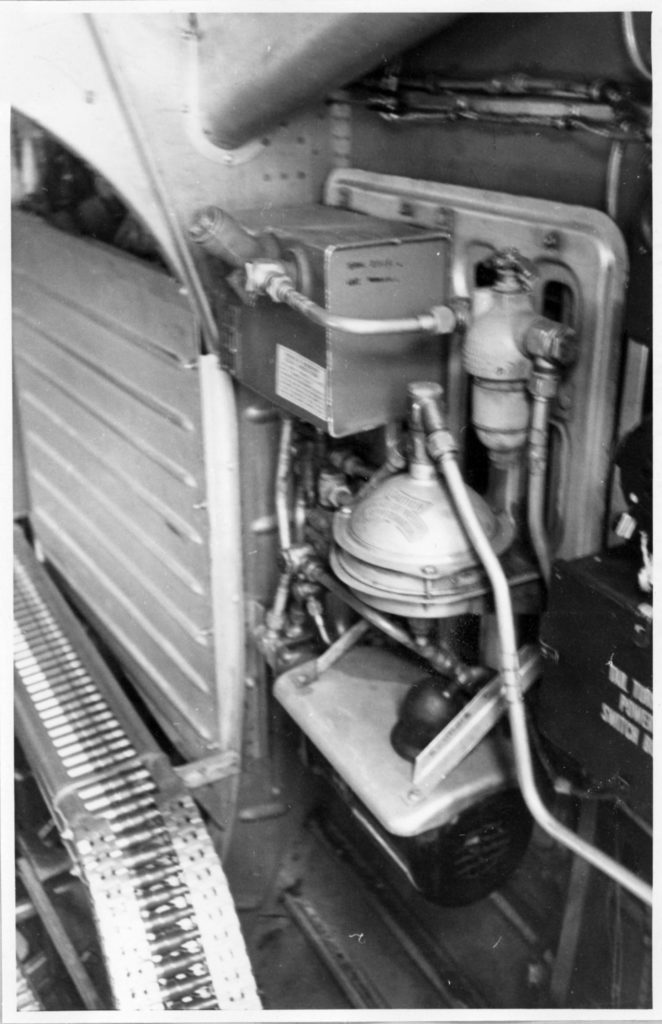
But, what about the images in the KU Report?  To be told more of Tell Me More, refer to the next post…


Deprecated: Function get_magic_quotes_gpc() is deprecated in /home3/emc2ftl3/public_html/wp-includes/formatting.php on line 4365